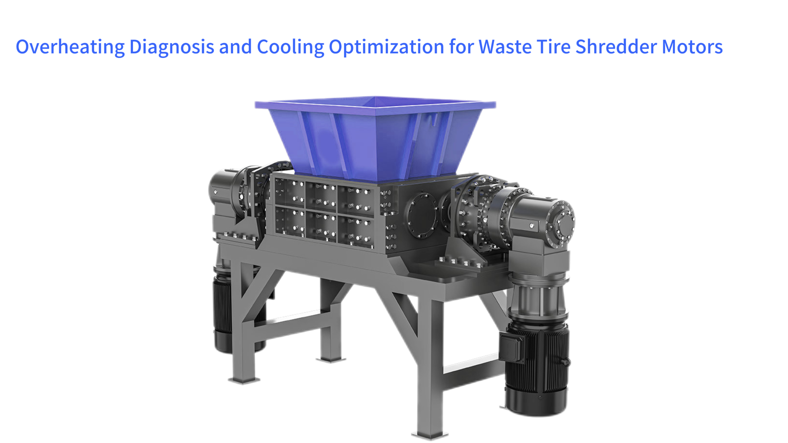
Industrial shredders, particularly those processing tough materials like tires, rely on powerful electric motors that can experience significant thermal stress during operation. Abnormal temperature rise in these motors is not just a performance issue; it's a primary cause of premature failure, unplanned downtime, and increased operational costs. This comprehensive guide explores the root causes of motor overheating, outlines advanced diagnostic techniques, and presents a matrix of optimization strategies for cooling systems. Understanding this thermal management challenge is crucial for maintaining the reliability and efficiency of a tire shredding operation, ensuring that the powerful drive units continue to function within their safe thermal limits even under the immense strain of shearing through steel-belted radials.
The consequences of unchecked motor heating are severe. For every 10°C that a motor operates above its rated temperature, the lifespan of its insulation system is halved. What begins as a slight increase in operating temperature can quickly cascade into a thermal runaway scenario, leading to insulation breakdown, bearing failure, and a catastrophic short circuit. A systematic approach to diagnosis and cooling is therefore an essential aspect of preventative maintenance, protecting a significant capital investment and ensuring continuous production throughput.
Core Cause Analysis of Motor Abnormal Temperature Rise
The phenomenon of abnormal temperature rise in shredder motors is rarely due to a single factor. It is typically the result of a complex interaction between electrical, mechanical, and environmental conditions. The primary sources of heat within an electric motor are categorized as copper losses (I²R losses in the windings), iron losses (hysteresis and eddy currents in the stator and rotor), and mechanical losses (friction in bearings). Any operational deviation that increases these losses will manifest as a rise in temperature.
External factors play an equally important role. The effectiveness of the motor's dedicated cooling system, whether it is air-based, liquid-based, or a combination, is paramount. A blockage in airflow, a drop in coolant flow rate, or degraded thermal interface materials can severely impede heat transfer. Furthermore, the quality of power supplied to the motor can introduce additional losses. Voltage imbalances and harmonic distortion from variable frequency drives (VFDs) can force the motor to draw more current to deliver the same torque, thereby generating excess heat.
Exponential Relationship Model Between Load Rate and Temperature Rise
The relationship between a motor's load and its temperature rise is not linear; it is exponential due to the nature of copper losses. Copper losses are proportional to the square of the current drawn by the motor (I²R). This means that if a motor is loaded to 120% of its rated capacity, the current draw increases by 20%, but the copper losses increase by approximately 44%. This rapid increase in heat generation quickly overwhelms the cooling system's capacity to dissipate it.
For example, a 200 kW motor designed for a double-shaft shredder may operate at 75°C above ambient at full load. If consistently overloaded to 240 kW, the temperature rise could exceed 110°C, pushing the winding temperatures dangerously close to the limit for Class F insulation (155°C). This model underscores the critical importance of correctly sizing the motor for the application and avoiding practices like using a smaller motor with a service factor to handle a continuous heavy load.
Numerical Simulation of Cooling Medium Flow Resistance
In liquid-cooled motors, the flow path of the coolant is complex, often involving narrow channels within the motor casing. Computational Fluid Dynamics (CFD) software is used to simulate the flow of coolant and identify areas of high flow resistance or stagnation. These simulations can model pressure drops, flow rates, and heat transfer coefficients across the entire system.
An analysis might reveal, for instance, that a sharp 90-degree bend in a cooling pipe is creating a significant pressure drop, reducing the overall flow rate from a designed 20 liters per minute to just 15 LPM. This reduction directly lowers the heat carrying capacity of the system. By redesigning the bend to a smoother, 45-degree angle, engineers can minimize the pressure drop, restore the design flow rate, and improve the cooling efficiency by 10-15%, all before any physical modifications are made.


Construction Method of the Motor Thermal Equivalent Circuit Model
To predict motor temperatures, engineers use a thermal equivalent circuit model, which treats heat flow like electrical current. In this model, heat sources (losses) are represented as current sources, thermal resistances (of insulation, air gaps, casing) are represented as resistors, and heat capacities (of the metal mass) are represented as capacitors. The temperature difference across a component is analogous to a voltage drop.
Building this model requires detailed knowledge of the motor's materials and construction. The thermal resistance from the windings to the stator, from the stator to the frame, and from the frame to the ambient air must all be calculated or measured. Once built, this model can be used to simulate transient and steady-state temperature conditions under various load profiles, allowing designers to identify thermal bottlenecks and optimize the cooling path before a physical prototype is even built.
Impact Test of Voltage Sag on Rotor Temperature Rise
Voltage sags, short-duration reductions in grid voltage, are a common power quality issue. During a sag, a motor will draw more current to maintain its torque output to keep the shredder rotor turning against the load. This increased current directly leads to higher copper losses and a rapid temperature rise in both the stator and the rotor. The rotor is particularly vulnerable as it is more difficult to cool.
Testing involves using a programmable power source to subject a motor to controlled voltage sags of specific depth and duration while monitoring rotor temperature with embedded sensors or through precise resistance measurements. A test might show that a 20% voltage sag for 500 milliseconds causes a rotor temperature spike of 15°C. This data is critical for setting protective relay thresholds that can disconnect the motor during severe sags to prevent thermal damage.
Thermal Effects of PWM Modulation in Variable Frequency Drives (VFDs)
VFDs control motor speed by using Pulse Width Modulation (PWM) to create a simulated sine wave. This output waveform contains high-frequency voltage components that can cause additional heating in the motor. These harmonics induce stray currents in the stator and rotor, creating parasitic losses known as stray load losses. The high switching frequency of modern VFDs (often 2-16 kHz) can also cause voltage reflections at the motor terminals due to impedance mismatch with the cable, leading to overvoltages that stress the insulation system and generate more heat.
The cumulative effect can be a 10-15% increase in motor temperature compared to operation on a pure sinusoidal power supply. Mitigation strategies include using output filters (dV/dt filters or sine wave filters), using inverter-duty motors with specially designed insulation systems, and ensuring proper cable selection and termination to minimize wave reflection phenomena.
Intelligent Diagnostic Technology System Construction
Moving beyond simple temperature alarms, modern diagnostic systems employ a multi-sensor, data-driven approach to predict and prevent motor overheating. These intelligent systems fuse data from temperature, vibration, current, and voltage sensors to build a comprehensive picture of motor health. By analyzing trends and correlations between these parameters, they can identify developing faults long before they lead to a critical temperature event.
The core of this system is a predictive analytics platform, often hosted on a cloud server or a local PLC control panel. This platform uses machine learning algorithms trained on historical operational data to establish normal baselines. Any deviation from these baselines, such as a gradual increase in operating temperature for a given load, triggers an alert, allowing for planned, proactive maintenance instead of reactive emergency repairs.
Distributed Temperature Measurement Scheme Using Fiber Bragg Grating Sensors
Fiber Bragg Grating (FBG) sensors represent a significant advancement over traditional thermocouples. A single optical fiber with multiple FBG sensors etched into it can be embedded along the length of the motor stator windings, providing a continuous temperature profile. Each FBG reflects a specific wavelength of light, which shifts proportionally with temperature changes.
This system can provide dozens of temperature measurement points along the windings, identifying localized hot spots that a single sensor would miss. For instance, an FBG array might detect a 20°C hot spot in one phase of the winding due to a failing connection, while the average temperature reading at the motor's periphery remains normal. This early warning allows for intervention before the fault escalates into a winding failure.
Finite Element Analysis of Motor End-Shield Temperature Field
The motor end-shields house the bearings and are critical for directing cooling airflow. Using Finite Element Analysis (FEA) software, engineers can create a detailed thermal model of the end-shield. The analysis simulates heat conduction through the metal and convection to the surrounding air, revealing temperature distributions and identifying areas where heat is effectively trapped.
An FEA might show that a particular ribbed design on the end-shield creates air pockets with little flow, leading to localized temperatures 30°C higher than adjacent areas. This insight allows for a redesign of the cooling fins or the addition of ventilation holes to promote better airflow, reducing bearing operating temperature and extending lubrication life.
Identification of Local Overheating Caused by Bearing Faults
Bearing failures are a leading cause of motor shutdowns. A faulty bearing increases friction, which generates excessive heat. This heat is initially localized to the bearing housing but can quickly conduct to the motor shaft and rotor. Vibration analysis is the primary tool for detecting bearing faults, but thermal imaging provides complementary evidence.
An infrared camera can detect a temperature differential of just 1°C between the drive-end and non-drive-end bearing housings. A bearing beginning to fail may show a temperature 5-10°C higher than its healthy counterpart. By correlating a specific vibration frequency (e.g., the Ball Pass Frequency Outer race) with a rising temperature trend at the bearing, the diagnostic system can confidently predict an impending bearing failure with high accuracy.
Early Warning of Thermal Runaway Caused by Insulation Aging
As motor insulation ages, its thermal conductivity decreases and its dielectric losses increase. This creates a vicious cycle: the older insulation is less able to conduct heat away from the copper windings, causing them to run hotter. The hotter temperatures further accelerate the aging of the insulation. This feedback loop can lead to thermal runaway.
Intelligent systems monitor for this by tracking the trend of the motor's operating temperature for a fixed, benchmarked load over time. A consistent upward drift of, for example, 0.5°C per month for the same output power is a clear indicator of progressive insulation degradation. This provides ample warning—often months or years—that the motor will eventually need rewinding or replacement before it fails catastrophically.
Ultrasonic Monitoring Technology for Coolant Flow Rate
In closed-loop liquid cooling systems, maintaining the correct flow rate is critical. Ultrasonic flow meters offer a non-invasive way to monitor flow without cutting into pipes or interrupting operation. These devices clamp onto the outside of a pipe and use the transit-time difference of ultrasonic signals to calculate the velocity of the fluid inside.
A continuous drop in flow rate, as detected by an ultrasonic sensor, can signal a clogged filter, a failing pump impeller, or an airlock in the system. By setting a lower alarm threshold at, say, 85% of the design flow rate, maintenance can be scheduled to clean or repair the cooling system during a planned outage, preventing an overheating event caused by inadequate cooling.
Cooling System Optimization Strategy Matrix
Once the causes of overheating are diagnosed, a range of optimization strategies can be deployed. The choice of strategy depends on the specific application, the severity of the thermal challenge, the available budget, and spatial constraints. There is no one-size-fits-all solution; often, a combination of approaches yields the best results. The matrix ranges from simple upgrades to existing air-cooling systems to the adoption of advanced liquid or phase-change cooling technologies.
The goal of optimization is not just to reduce temperature, but to do so efficiently. An optimized system maintains the motor within its ideal temperature range with the lowest possible energy expenditure from fans, pumps, or other cooling auxiliaries. This involves careful design of heat exchangers, selection of efficient motors for cooling components, and intelligent control that modulates cooling effort based on real-time thermal demand.
Optimization Design Guidelines for Finned Heat Sinks
Finned heat sinks are ubiquitous in air-cooled motors. Their design involves balancing multiple factors: the number of fins, fin height, fin thickness, and the base plate thickness. Increasing the number of fins increases surface area but can also restrict airflow if they are too closely spaced. Computational Fluid Dynamics (CFD) and thermal analysis are used to find the optimal geometry.
For a TEFC (Totally Enclosed Fan Cooled) motor on a shredder, an optimized fin design might increase the surface area for heat dissipation by 25% without increasing the overall motor size. This redesign could lower the motor's operating temperature by 10-15°C under full load, significantly extending the life of the insulation and bearings. The material of the heat sink, often aluminum for its excellent thermal conductivity, is also a key consideration.
Turbulence Enhancement Technology for Water-Cooling Plate Channels
The efficiency of a water-cooling plate is determined by how effectively the coolant absorbs heat from the metal surface. Laminar flow, where water moves in smooth, parallel layers, is poor for heat transfer because a boundary layer of stagnant fluid acts as an insulator. Turbulent flow breaks up this boundary layer, dramatically improving heat transfer.
Engineers design channels with features like dimples, ribs, or serpentine paths to disrupt the flow and induce turbulence. While this increases the pressure drop (requiring a more powerful pump), the enhancement in heat transfer coefficient can be over 200%. For a high-power motor, this might mean the difference between a stable 80°C operating temperature and a dangerous 110°C, ensuring reliable operation during the most demanding shredding tasks.
Filtration and Heat Exchange Balance in Oil Cooling Systems
Oil cooling is highly effective but introduces the challenge of maintaining oil cleanliness. Contaminants like metal wear particles can clog small cooling channels and reduce the oil's thermal properties. A closed-loop oil system must include a filtration unit. However, the filter itself creates a pressure drop and requires a bypass valve to prevent damage if it becomes clogged.
The system must be balanced. The filter must be fine enough to protect the cooling channels (e.g., 10-micron rating) but not so fine that it clogs too quickly. The oil-to-water heat exchanger must be sized to reject the full heat load of the motor losses. For a 500 kW shredder motor, this could mean designing a system that circulates 50 liters of oil per minute through a filter and a heat exchanger capable of dissipating 15 kW of thermal power to the facility's cooling water loop.
Integration of Heat Pipe Technology in Motor End-Shields
Heat pipes are passive heat transfer devices that can move large quantities of heat with minimal temperature difference. They are sealed tubes containing a working fluid that evaporates at a hot spot, travels to a cooler section of the pipe, condenses, and then returns via capillary action in a wick structure. Integrating heat pipes into motor end-shields is an innovative way to tackle bearing overheating.
One end of the heat pipe is embedded in the bearing housing, while the other end is exposed to the ambient air or attached to an external heat sink. This system can passively reduce bearing operating temperature by 15-20°C without any moving parts or external power. This is particularly valuable in environments where dust and debris can clog traditional fan-based cooling fins, making them a robust solution for shredding operations.
Application of Nanofluids in Cooling Systems
Nanofluids are engineered colloids made by suspending nanometer-sized solid particles (e.g., copper oxide, aluminum oxide, or carbon nanotubes) in a base fluid like water or oil. These particles dramatically increase the thermal conductivity of the fluid. A nanofluid with just a 1-5% volume fraction of nanoparticles can exhibit a 20-40% improvement in thermal conductivity compared to the base fluid alone.
In a motor cooling application, using a water-based nanofluid in a jacket cooling system can significantly enhance the heat transfer from the motor casing to the coolant. This allows for a more compact heat exchanger or a lower coolant flow rate for the same cooling performance, reducing the energy consumed by the cooling pump. While currently a more expensive solution, it represents a cutting-edge approach to thermal management for the most demanding applications.
Efficiency Improvement and Cost Balance
Investing in advanced cooling and motor technology is not just about preventing failure; it is also a powerful strategy for reducing operational expenses. Energy costs often represent the largest portion of a motor's total lifetime cost. Therefore, any improvement in system efficiency, whether in the motor itself or its cooling auxiliaries, offers a rapid return on investment through lower electricity bills.
The decision-making process involves a holistic Life Cycle Cost (LCC) analysis. This analysis weighs the higher initial capital expenditure (CAPEX) for premium-efficiency equipment against the long-term savings in operational expenditure (OPEX) from reduced energy consumption and lower maintenance costs. Government incentives and carbon footprint reduction targets are increasingly making the case for investing in the most efficient technologies available.
Dynamic Allocation Algorithm for Copper and Iron Losses
In motors controlled by advanced VFDs, there is a trade-off between copper and iron losses. Copper losses dominate at high loads, while iron losses dominate at light loads and high speeds. Sophisticated control algorithms within the drive can dynamically adjust the motor's magnetic flux level to minimize the sum of these losses at any given operating point.
This "loss minimization control" strategy might slightly reduce the torque per amp at light loads but can improve overall efficiency by 2-5% across the motor's operating range. For a 200 kW motor running 6,000 hours a year, a 3% efficiency gain translates to over 36,000 kWh in annual energy savings, significantly reducing operating costs and the motor's thermal footprint.
PWM Speed Control for Cooling Fans
The fans on air-cooled motors are often running at full speed regardless of the motor's actual temperature. This wastes energy and creates unnecessary noise. Implementing PWM control for the fan motor allows its speed to be modulated based on the temperature of the motor windings or bearings.
A temperature sensor provides feedback to the control system. When the motor is cool, the fan may run at only 40% speed, consuming a fraction of the power. As the temperature rises, the fan speed ramps up proportionally. This can reduce the average energy consumption of the cooling fan by 50% or more, and it also reduces the wear on the fan bearings, extending their service life.
Optimization Scheme for Pump Variable Frequency Drive
The pumps in liquid cooling systems are classic candidates for VFD optimization. The affinity laws state that the power required by a pump is proportional to the cube of its speed. This means that reducing the pump speed by 20% reduces the power consumption by nearly 50%.
In a cooling system, a VFD on the pump can be controlled to maintain a constant pressure differential or a constant temperature difference across the motor. As the thermal load on the motor decreases, the VFD slows the pump down, dramatically cutting energy use. This is far more efficient than using a constant speed pump with a bypass valve to regulate flow, which wastes energy by throttling.
Synergistic Design of Motor and Cooling System
The highest efficiency is achieved when the motor and its cooling system are designed together as an integrated system, not as separate components. This co-design approach allows engineers to optimize the thermal interfaces, minimize flow resistance, and match the cooling capacity precisely to the heat generation profile of the motor.
For instance, the stator laminations can be designed with cooling channels cast directly into them, bringing the coolant into intimate contact with the primary heat source. This integrated liquid cooling approach can handle power densities that are impossible for air cooling, allowing for a smaller, more powerful motor for the same physical footprint, which is a critical advantage in space-constrained industrial settings like mobile shredding stations.
Application of Carbon Footprint Accounting in Technology Selection
Beyond direct financial cost, there is a growing emphasis on the carbon footprint of industrial operations. The selection of motor and cooling technology can have a significant impact on Scope 2 emissions (from purchased electricity). A high-efficiency motor and an optimally controlled cooling system consume less electricity, directly reducing the CO2 emissions associated with their operation.
When comparing two cooling options, a carbon footprint analysis quantifies the lifetime CO2 emissions of each. For example, an advanced liquid cooling system might have a slightly higher embodied carbon (from manufacturing) but save thousands of tons of CO2 over its 20-year lifespan through reduced energy consumption. This analysis supports both environmental goals and corporate social responsibility reporting, making it an increasingly important factor in the technical decision-making process.
Safety Protection and Standard Compliance
Ensuring the safe operation of high-power motors in shredders is a non-negotiable requirement governed by a web of international standards and certifications. These standards define the rules for construction, testing, and protection to prevent fires, explosions, and electrical hazards caused by overheating. Compliance is not merely a legal obligation; it is a fundamental aspect of risk management and protecting both personnel and capital assets.
The safety system is multi-layered, incorporating built-in motor protection features like thermal protectors, external monitoring devices such as temperature sensors and current relays, and overarching control logic within the plant's PLC. This system is designed to provide graduated responses: a warning at a lower temperature threshold, a controlled shutdown at a higher threshold, and an immediate emergency stop in the event of a critical fault.
Selection Basis for Motor Insulation Class (Class F/H)
Motor insulation classes are defined by the maximum operating temperature they can withstand. Common classes are B (130°C), F (155°C), and H (180°C). The class defines the thermal margin designed into the motor. For a demanding application like a shredder, a Class F or H insulation system is standard. This allows the motor to handle occasional overloads and higher ambient temperatures without degrading the insulation.
The rule of thumb is to select an insulation class that provides at least a 25°C margin above the expected maximum operating temperature. For instance, if a motor is expected to run at 120°C, a Class F system (155°C limit) is appropriate. This margin accounts for measurement errors, localized hot spots within the windings, and the gradual aging of the insulation over time, ensuring long-term reliability and safety.
Action Characteristic Curves of Thermal Protectors
Thermal protectors, either bimetallic or solid-state, are critical safety devices embedded in the motor windings. Their operation is defined by a time-current characteristic curve. This curve shows how quickly the protector will trip at a given level of overcurrent. A "Class 10" protector, for example, must trip within 10 seconds at 600% of the motor's full-load current.
These curves must be carefully coordinated with the motor's thermal capacity. The protector must trip fast enough to prevent the windings from exceeding their insulation class temperature during a locked-rotor event, but it must not trip during the motor's normal start-up, which also involves a high inrush current. This coordination ensures the motor is protected without causing nuisance tripping that disrupts production.
Cooling Design Challenges for Explosion-Proof Motors
In environments where combustible dust from shredded materials may be present, explosion-proof (ATEX/EX-rated) motors are required. These motors are designed to contain any internal explosion and prevent it from igniting the surrounding atmosphere. This design requirement imposes significant constraints on cooling.
The motor enclosure must be robust and have specially designed flanges that cool any escaping gases below the ignition temperature of the external atmosphere. This makes air-to-air heat exchange less efficient. As a result, explosion-proof motors often run hotter than standard motors of the same power and may require derating (using a larger motor for a given load) or the use of external cooling methods to stay within safe temperature limits.
Setting Principles for High-Temperature Alarm Thresholds
A sophisticated protection system uses tiered temperature alarms. A first-stage warning alarm is typically set 10-15°C below the motor's maximum allowable operating temperature. This gives operators a chance to investigate and respond to a developing problem, such as reducing the shredder load or checking the cooling system, before a shutdown is necessary.
The second-stage shutdown alarm is set just below the critical temperature limit of the insulation. The setting must account for the thermal inertia of the motor; after a shutdown command is issued, the temperature will continue to rise for a short period. Therefore, the shutdown threshold might be set at 145°C for a Class F motor, providing a 10°C buffer to prevent the temperature from overshooting and causing damage during the cooldown period.
Redundant Design of Emergency Cooling Systems
For critical applications where an unscheduled shutdown would be extremely costly or hazardous, redundant emergency cooling systems are implemented. This is a "safety-in-depth" approach. The primary cooling might be a water-based system. The redundancy could be a backup air blast system—a powerful fan that is activated if the water flow is lost or if the motor temperature approaches a critical level despite the primary cooling.
This system is fed from an uninterruptible power supply (UPS) to ensure it functions even during a main power failure. The control logic for engaging the emergency cooling is separate from the main PLC to avoid common-cause failures. This redundancy ensures that every possible avenue is explored to cool the motor and prevent a catastrophic failure, buying valuable time for a controlled shutdown process.
Optimization Cases for Typical Application Scenarios
The optimal approach to motor cooling is highly dependent on the specific operating environment and application of the shredder. A solution that works perfectly in a temperate climate may fail miserably in the tropics or at high altitude. Real-world optimization requires a deep understanding of these external factors and a tailored approach that addresses the unique challenges they present.
Case studies from around the world provide valuable insights into successful strategies. These cases illustrate the importance of environmental adaptation, from dealing with extreme heat and dust to overcoming the challenges of cold weather and corrosive atmospheres. The most effective solutions often combine appropriate technology selection with clever operational adjustments.
Daily Throughput Optimization for Southeast Asian Rubber Plantations
Shredders operating in the humid, hot climate of Southeast Asia face severe cooling challenges. High ambient temperatures reduce the cooling system's temperature delta (ΔT), its driving force for heat rejection. Here, optimization focuses on shifting the operational schedule. The highest throughput shredding is scheduled for the cooler nighttime hours, when ambient temperatures might be 28°C instead of the daytime 38°C.
During the day, the shredder may be operated at a reduced load, perhaps 80% of capacity, to limit heat generation. This operational strategy, combined with oversized cooling radiators and frequent cleaning of cooling fins to remove pollen and dust, allows for continuous operation without overheating, maximizing total daily throughput while protecting the equipment.
Heat Dissipation Improvement Case for Shredders on the Tibetan Plateau
At high altitudes, such as mining operations on the Tibetan Plateau, the thin air presents a dual problem for air-cooled motors. First, the reduced density of the air lowers its heat carrying capacity. Second, the lower oxygen content can cause problems for the combustion engines that often power mobile shredding units. The solution for the electric motors is to use pressurized cooling systems.
A sealed, pressurized air-cooling circuit is employed. A fan forces the less-dense air through the cooler, but because the system is pressurized, the density of the air at the point of heat exchange is maintained closer to sea-level conditions. This engineering adaptation prevents the motor from derating significantly at altitude, ensuring it can still deliver its full power and torque for the shredding process.
Dust Protection Design for Desert Environments
In desert environments, fine, abrasive sand is the primary enemy of air-cooled motors. It can clog cooling fins, abrade fan blades, and infiltrate bearing housings. The optimization strategy here is all about filtration and sealing. Motors are specified with a high IP (Ingress Protection) rating, such as IP65, indicating they are dust-tight and protected against water jets.
The cooling air intake is equipped with multi-stage filters: a coarse pre-filter to catch larger particles and a high-efficiency primary filter. These filters are designed for easy access and frequent maintenance. Furthermore, the cooling system may be designed to create a slight positive pressure inside the motor enclosure to prevent dust from being drawn in through any small gaps or seals, a highly effective method for keeping abrasive particles out of critical components.
Preheating Scheme for Cooling Systems in Northeast China Winters
In the frigid winters of Northeast China, the challenge is preventing cooling rather than enhancing it. If a motor is started in temperatures below -20°C, the lubricant in its bearings can be too viscous, and the sudden inrush of current into cold windings can cause mechanical and thermal stress. The cooling system itself, if water-based, is at risk of freezing.
The optimization involves a comprehensive preheating system. Trace heaters are wrapped around the motor casing and cooling pipes to maintain a base temperature of around 5°C when the equipment is idle. The cooling fluid is mixed with a propylene glycol antifreeze solution. The control system will not allow the motor to be started until sensors confirm that the temperatures of the windings, bearings, and coolant are all above their minimum safe thresholds, preventing cold-start damage.
Anti-Corrosion Cooling Measures for Coastal Salt Spray Environments
Salt-laden air in coastal areas is highly corrosive to aluminum heat sinks, copper windings, and steel motor frames. Standard components will succumb to rapid corrosion. The optimization requires the selection of specific materials and coatings. Motors and coolers are specified with corrosion-resistant coatings, often using epoxy paints or stainless steel components.
Aluminum heat sinks are treated with anodization. Electrical connections are plated with nickel or tin to prevent oxidation. The cooling system must be designed to be easily rinsed with fresh water to remove salt deposits during routine maintenance. This focus on corrosion resistance extends the service life of the motor and its cooling system in a harsh environment that would otherwise quickly degrade standard equipment.
Future Technology Development Trends
The field of motor thermal management is on the cusp of a revolution driven by advancements in materials science, artificial intelligence, and connectivity. The future will see cooling systems that are not just passive components but active, intelligent partners in optimizing motor performance and health. These technologies will enable higher power densities, greater efficiency, and unprecedented levels of reliability and predictive maintenance.
Emerging trends point towards fully integrated systems where the boundaries between the motor, its cooler, and its control system become blurred. These systems will use real-time data and predictive algorithms to autonomously manage thermal conditions, adapting to changing loads and environments to always maintain optimal performance while minimizing energy consumption. The goal is a self-regulating thermal system that requires minimal human intervention.
Application of Deep Learning Algorithms in Temperature Rise Prediction
Future diagnostic systems will utilize deep learning neural networks to predict motor temperature rise with incredible accuracy. These models will be trained on vast datasets encompassing motor electrical parameters, environmental conditions, load profiles, and historical failure modes. The AI will learn complex, non-linear relationships that are impossible to model with traditional physics-based equations alone.
Such a system could predict the motor's temperature 30 minutes into the future based on the current shredder load and the forecasted ambient temperature change. It could then proactively adjust the cooling system speed or suggest a slight reduction in feed rate to avoid a thermal overload, moving from reactive protection to truly predictive and prescriptive management.
Application of Ultra-Thin Graphene Coating Heat Dissipation Technology
Graphene, a single layer of carbon atoms arranged in a hexagonal lattice, has extraordinary thermal conductivity—far superior to copper. Research is focused on developing practical methods to apply graphene coatings to motor components. A thin graphene layer applied to the interface between the stator windings and the motor housing could dramatically reduce the thermal resistance at this critical junction.
This would allow heat to be pulled away from the windings more effectively, lowering the hotspot temperature for the same level of losses. While currently in the R&D phase, this technology holds the promise of enabling smaller, more powerful motors or allowing existing motors to handle significant overloads without any change to their external cooling systems.
Feasibility of Magnetic Refrigeration Technology for Motor Cooling
Magnetic refrigeration is a nascent cooling technology that uses the magnetocaloric effect—where certain materials heat up when magnetized and cool down when removed from the magnetic field. This solid-state technology has the potential to be more efficient and quieter than traditional compressor-based refrigeration cycles.
While currently not feasible for entire motor cooling, it could be applied in the future to create ultra-high-performance cooling loops for critical hotspots within a motor, such as the end-windings. This would represent a paradigm shift, moving from transporting heat to actively "pumping" it away using magnetic fields, offering a new tool for thermal management in extreme applications.
Application of Blockchain in Equipment Thermal State Traceability
Blockchain technology offers a secure, immutable ledger for recording data. In the context of motor thermal management, every significant thermal event—an overload, a cooling system fault, a scheduled maintenance action—could be recorded as a "transaction" on a blockchain associated with that specific motor's digital twin.
This creates a verifiable and tamper-proof lifetime history of the motor's thermal health. This record would be invaluable for warranty claims, resale valuation, and regulatory compliance. It provides complete transparency, allowing any stakeholder to verify that the motor has been operated within its thermal limits throughout its entire service life.
Transformation of Space-Grade Thermal Control Materials to Industrial Applications
The aerospace industry develops advanced materials for thermal control in the extreme environment of space. These include lightweight composite heat pipes, high-emissivity coatings, and phase-change material (PCM) packages that absorb large amounts of heat during melting. As the production costs of these materials decrease, they are beginning to trickle down into high-end industrial applications.
We may soon see motors equipped with PCM packages that absorb heat during short-term overloads, preventing temperature spikes. Similarly, aerospace-grade thermal coatings could be applied to motor casings to enhance radiative heat loss. This cross-pollination of technology from space to industry will provide a new suite of tools for solving the most challenging thermal problems in heavy machinery like tire shredders.