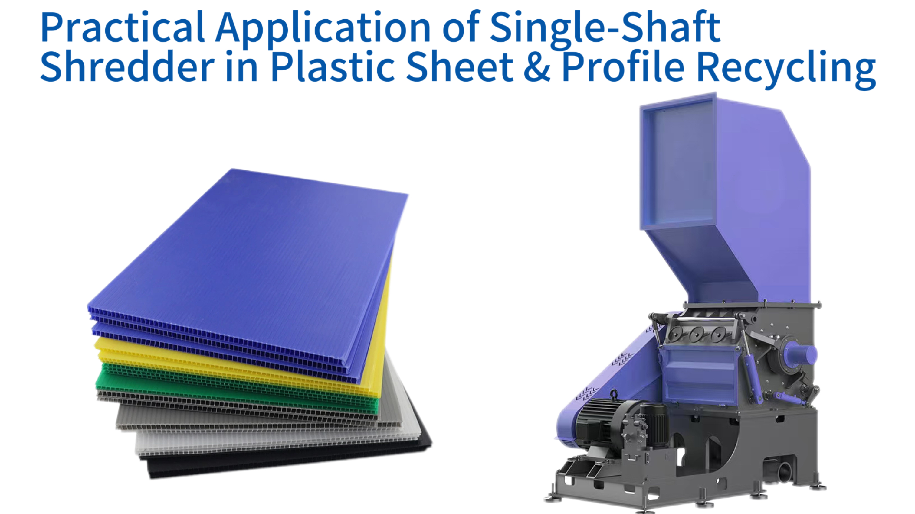
The recycling of plastic sheets and profiles represents a significant segment of the global plastics recovery effort. These materials, often derived from construction offcuts, window frames, pipes, and industrial packaging, present unique challenges due to their size, rigidity, and varied composition. A single-shaft shredder has emerged as a pivotal machine in this domain, engineered to reduce such bulky items into uniform, manageable fragments. This initial size reduction is the gateway to further processing stages like washing, agglomeration, and pelletization. The technology behind these machines has evolved over decades to handle the tough demands of modern recycling facilities. By understanding how a single-shaft shredder functions and where it fits within the broader recycling line, operators can maximize throughput and material quality. This article explores the practical application of this equipment, detailing its design, operational workflow, maintenance needs, and the innovations shaping its future. For companies like MSW Technology, with fifteen years of experience in the field, the continuous refinement of these machines reflects a deep commitment to efficient and sustainable plastic waste management.
Understanding the Single-Shaft Shredder Design and Mechanism
Core Components of Single-Shaft Shredder
| Component | Key Specifications |
|---|---|
| Rotor Speed | 70 - 150 rpm (adjustable) |
| Motor Power | 30 kW - 200+ kW |
| Screen Aperture | 10 mm - 50 mm (replaceable) |
| Blade Material | D2 Tool Steel, HSS, Carbide-tipped |
The single-shaft shredder operates on a principle that combines shear, tearing, and compression to break down materials. Unlike dual-shaft machines that intermesh, the single-shaft design uses a rotating rotor equipped with cutting blades working against a fixed counter-knife. A hydraulically driven ram continuously pushes the material against the rotor, ensuring consistent feed and processing. This configuration is particularly effective for plastics, which can be tough and elastic. The design prioritizes controlled output size and energy efficiency, making it a staple in plastic sheet and profile recycling lines worldwide. The following sections break down the core elements that define this machinery.
Core Components and Their Functions
Every single-shaft shredder comprises several key components that work in harmony. The main structure is a heavy-duty steel frame that houses the cutting chamber and supports the drive train. Inside the chamber, the rotor is the heart of the machine, carrying rows of interchangeable cutting blades. Opposite these blades, a stationary bed knife is mounted to the frame, creating the cutting action as the rotor turns. A hydraulic ram, positioned above or to the side, advances the material toward the rotor at a controlled speed. Beneath the rotor, a replaceable screen mesh determines the final particle size by allowing properly sized material to pass through. The drive system, typically consisting of an electric motor and a gearbox, provides the necessary torque to rotate the heavy rotor. A control panel with a programmable logic controller (PLC) manages all functions, from ram pressure to rotor speed, ensuring smooth operation and safety. Each of these parts is designed for durability and easy maintenance, recognizing that the materials processed can be abrasive and demanding. At MSW Technology, the integration of robust components reflects fifteen years of learning what withstands the test of time in industrial recycling environments.
Materials of construction are carefully selected. The rotor is often machined from solid steel to provide a rigid base for the blades. Cutting blades are manufactured from specialized tool steels or tungsten carbide for edge retention. The screen mesh is made from wear-resistant steel plate with precisely punched holes. The hydraulic system includes a pump, valves, and a cylinder, all rated for continuous industrial use. Proper selection of these components ensures that the shredder can handle the high stresses of processing thick plastic sheets and profiles without frequent breakdowns. For example, in processing PVC window frames, the combination of sharp blades and a sturdy rotor prevents the material from simply deforming and wrapping around the shaft.
The Rotor and Blade Configuration
The rotor design is critical to shredder performance. Most single-shaft shredders use a rotor that is either circular or hexagonal in cross-section, with blade holders arranged in a staggered pattern. This stagger ensures that the cutting load is distributed evenly, reducing vibration and peak torque demands. Blades can be replaced individually when worn, minimizing downtime. The number of blade rows varies by machine size and application, typically ranging from two to six rows. The cutting geometry includes the rake angle and clearance between the rotor blades and the bed knife; these angles are optimized for the type of plastic being processed. For brittle plastics like polystyrene, a sharper rake angle may be used, while for tough, flexible materials like polyethylene, a more robust blade shape with a larger clearance prevents clogging. The rotational speed of the rotor is also adjustable; lower speeds generate higher torque for thick materials, while higher speeds can increase throughput for softer sheets. The engineering behind rotor and blade configuration directly influences the particle size distribution and energy consumption of the shredding process.
Blade materials have advanced significantly. High-speed steel, D2 tool steel, and carbide-tipped blades offer different balances of toughness and wear resistance. For recycling plastic sheets that may contain fillers or contaminants like glass fibers, blade wear can be accelerated. In such cases, opting for a harder blade material extends the intervals between sharpening. Some shredders feature a cassette-style blade mounting system that allows for quick changeouts outside the machine, keeping production running. The blade configuration also determines the machine's ability to handle large, flat sheets; a well-designed rotor will grab the sheet and pull it into the cutting zone without jamming. This is where the experience of a manufacturer like MSW Technology becomes evident, as their rotor designs have been refined over fifteen years to handle a wide variety of feedstock.
The Hydraulic Ram Pushing System
The hydraulic ram is what distinguishes single-shaft shredders from other types. It serves as a positive feeding mechanism, ensuring that material is continuously presented to the rotor. The ram is controlled by a PLC that monitors the motor load. If the motor current rises, indicating a heavy cutting load, the ram retracts slightly or pauses to allow the rotor to clear the material. Conversely, when the load drops, the ram advances to push more material. This closed-loop control maximizes throughput while preventing overloading. The ram face is often fitted with wear plates that can be replaced when worn. The speed and force of the ram are adjustable based on the material density and desired output. For thick plastic profiles, a higher pushing force may be required, while for thin sheets, a faster cycling speed can improve efficiency. The hydraulic system also includes a cooling circuit to maintain oil temperature within safe limits during extended operation.
This pushing action is particularly beneficial for processing long plastic profiles, such as pipes or window frames. The ram holds the material against the rotor, preventing it from bouncing or moving away from the cutting zone. Without such a system, the rotor might simply push the material around the chamber without effective size reduction. The PLC also allows for programming different feeding patterns; for instance, a “dwell” period can be introduced to allow the rotor to clear the cutting chamber before the ram advances again. This intelligent control reduces the risk of jams and ensures a consistent output. MSW Technology's shredders incorporate advanced hydraulic control algorithms developed over fifteen years of field experience, optimizing the balance between productivity and energy use.
The Screen Sizing Control
Below the rotor, a screen acts as a classifier. Only particles small enough to pass through the screen apertures exit the cutting chamber; larger particles are retained and subjected to further cutting. The screen size directly determines the final fragment dimensions. For plastic sheet and profile recycling, typical screen apertures range from 10 mm to 50 mm, depending on downstream requirements. A smaller screen produces finer material, which may be suitable for direct extrusion or washing, but reduces throughput. A larger screen increases output but may produce particles that need secondary grinding. The screen is usually made of thick steel plate with holes that are either round or square, arranged in a staggered pattern to maximize open area while maintaining structural strength. Screens are replaceable, allowing the same shredder to be configured for different applications.
The interaction between the rotor, blades, and screen is complex. As material is cut, it is forced against the screen by the rotor's motion. Some particles may pass immediately, while others recirculate until sufficiently reduced. The clearance between the blade tips and the screen affects the cutting efficiency; too much clearance leaves a layer of uncut material, while too little can cause excessive blade wear. Modern shredders allow adjustment of this clearance. Additionally, some machines feature a “screen cradle” that can be hydraulically lowered for screen changes, reducing maintenance time. The screen also serves to dampen noise and contain dust within the cutting chamber. In applications processing heat‑sensitive plastics like PVC, the screen design must allow adequate airflow to prevent material from melting and clogging the apertures.
Drive System and Power Transmission
The drive system of a single‑shaft shredder must deliver high torque at low speeds. Typically, an electric motor drives a gearbox, often a planetary or helical design, that reduces speed and multiplies torque. Motor power can range from 30 kW for smaller units to over 200 kW for large‑scale industrial shredders. The gearbox must be robust enough to handle shock loads as tough materials enter the cutting zone. Many shredders also incorporate a flywheel on the rotor shaft to store kinetic energy, helping to smooth out power demands and reduce peak loads on the motor. The electrical cabinet houses starters, frequency drives for speed control, and the PLC. Modern drives allow precise control of rotor speed, enabling the operator to adjust to different materials. For instance, processing rigid plastic profiles may benefit from slower speeds with higher torque, while softer sheets can be run faster to increase throughput.
Energy efficiency is a key consideration. The combination of a correctly sized motor, efficient gearbox, and intelligent load sensing can significantly reduce power consumption per ton of material processed. Some systems use dual motors or direct drive configurations to further improve efficiency. The drive system also includes safety features such as thermal overload relays and emergency stops. For facilities processing large volumes, the reliability of the drive train is paramount; downtime for gearbox repairs can be costly. Manufacturers like MSW Technology often incorporate oversized bearings and hardened gears, drawing on fifteen years of experience to ensure longevity. The drive system is typically located externally to the cutting chamber, protected from dust and debris, with proper ventilation for cooling.
Control Systems and Automation
Modern single‑shaft shredders are equipped with advanced control systems that monitor and adjust operation in real time. A PLC with a touchscreen interface allows operators to set parameters such as rotor speed, ram pressure, and cycle times. Sensors monitor motor amperage, bearing temperatures, hydraulic pressure, and oil levels. The control logic automatically adjusts the ram to maintain optimal load, preventing overloads and maximizing throughput. Alarms alert operators to abnormal conditions, such as high temperature or low oil level. Many systems also include remote monitoring capabilities, allowing plant managers to track performance and diagnose issues via the internet. This level of automation reduces the need for constant operator attention and improves overall equipment effectiveness (OEE).
Automation also enhances safety. Interlocks prevent the machine from starting when access doors are open. Emergency stop buttons are placed at strategic locations. The PLC can record operational data, such as running hours, energy consumption, and maintenance intervals, facilitating predictive maintenance. For recycling operations that are part of a larger integrated plant, the shredder’s control system can communicate with upstream and downstream equipment, coordinating material flow. For example, if a downstream granulator becomes full, the shredder can automatically pause feeding. This integration minimizes manual intervention and ensures smooth, continuous operation. MSW Technology's shredders feature intuitive control panels developed over fifteen years of user feedback, making them accessible to operators of varying skill levels while providing advanced functionality for experienced users.
Why Single-Shaft Shredder Suits Plastic Sheet and Profile Recycling
Plastic sheets and profiles, whether from post‑industrial scrap or post‑consumer waste, possess characteristics that make them well‑suited to single‑shaft shredding. Their large surface area and often rigid structure require a machine that can grab and pull material into the cutting zone consistently. The single‑shaft design, with its hydraulic ram and high‑torque rotor, excels at this task. Additionally, the ability to control output size precisely through screen selection aligns with the needs of downstream processes like washing and extrusion. This section explores the specific advantages that make the single‑shaft shredder the preferred choice for this material stream.
Handling Large and Bulky Plastic Items
Plastic sheets used in signage, packaging, or construction can be several meters in length and width. Profiles such as window frames, pipes, and sidings are similarly unwieldy. Single‑shaft shredders are designed with large hopper openings that accept these bulky items without pre‑cutting. The hydraulic ram then pushes the material into the rotor, which gradually reduces it. This eliminates the need for manual pre‑processing, saving labor costs and improving safety. The robust construction of the shredder, including thick chamber walls and a heavy rotor, withstands the impact of large, rigid items. For example, a whole PVC window frame can be fed directly; the ram holds it steady while the rotor cuts through the corners and straight sections. This capability is essential for recycling facilities that receive mixed loads of bulky waste. The design also minimizes the risk of material bridging or clogging, as the ram forces material down even when the chamber is full.
Compared to other shredder types, the single‑shaft model offers superior control over the feed rate. The ram speed can be adjusted to match the cutting capacity, preventing overloading. In contrast, a dual‑shaft shredder might struggle with long profiles that can wrap around the shafts. The single‑shaft’s anvil and rotor arrangement cuts rather than tears, producing cleaner edges and fewer fines. For plastic sheets that are thin but large, the ram ensures they are crumpled and fed into the rotor rather than simply flapping around. This results in a more consistent output and higher throughput. Facilities processing such materials often rely on the dependability of single‑shaft shredders from experienced manufacturers like MSW Technology, whose fifteen years in the industry have yielded designs that handle even the most awkward‑shaped plastics efficiently.
Consistent Output Size for Downstream Processing
After shredding, the plastic fragments typically undergo washing, separation, and granulation before being converted into pellets or new products. The size and uniformity of the shredded material directly affect the efficiency of these downstream steps. A single‑shaft shredder equipped with a screen produces particles of a defined maximum size. This consistency ensures that washing equipment can remove contaminants effectively and that granulators or agglomerators can process the material without jamming or excessive wear. For instance, if the shredder output contains oversized flakes, they may block the screen in a wet granulator, causing downtime. Conversely, too many fines can be lost in the washing water or create dust problems. By selecting the appropriate screen, operators can tailor the particle size to the exact specifications of their downstream machinery.
The controlled output also benefits material handling. Uniform flakes flow more easily through conveyors and silos, reducing blockages. In extrusion, consistent flake size promotes even melting and stable processing. For plastic sheet and profile recycling, where the feedstock may consist of different polymers and colors, having a uniform particle size simplifies sorting and blending. Some advanced recycling lines integrate the shredder with screening and recirculation systems, where oversize particles are automatically returned to the shredder for further reduction. This closed‑loop approach ensures that all material meets the target size specification. The ability to achieve such consistency is a hallmark of well‑engineered single‑shaft shredders, and MSW Technology's fifteen years of application knowledge allow them to recommend the optimal screen and blade setup for each unique recycling stream.
Energy Efficiency and Operational Cost
Energy consumption is a major operating expense in any recycling plant. Single‑shaft shredders are inherently more energy‑efficient for plastic sheet and profile applications compared to some alternatives because they use a controlled feeding mechanism that matches the cutting load. The hydraulic ram adjusts to maintain the motor at near‑optimal load, avoiding the inefficiencies of running under light load or stalling under overload. The use of a flywheel also helps smooth out energy demand, reducing peak power charges. Additionally, the single‑shaft design generates fewer fines than high‑speed granulators, meaning less material is lost as dust, which represents both a material loss and an energy waste. Over the course of a year, these efficiency gains can translate into significant cost savings.
Operational costs also include blade maintenance and wear parts. Because the single‑shaft shredder operates at low speed, blade wear is generally lower than in high‑speed machines. The blades are also designed for multiple re‑sharpening, extending their useful life. The hydraulic system, while requiring periodic maintenance, is reliable and long‑lasting when properly cared for. Overall, the total cost of ownership for a single‑shaft shredder can be lower than for other technologies, especially when processing the tough materials found in plastic sheets and profiles. MSW Technology, with fifteen years of experience, has refined its shredders to minimize energy use and maximize component life, providing customers with a cost‑effective solution that aligns with sustainability goals.
Low Noise and Dust Generation
Recycling facilities often operate in environments where noise and dust regulations are stringent. Single‑shaft shredders, operating at low rotational speeds (typically 80–120 rpm), generate significantly less noise than high‑speed hammer mills or granulators. The cutting action is a shearing process rather than an impact, which inherently produces less airborne dust. Moreover, the screen and enclosed chamber contain most of the dust, and many machines can be fitted with soundproof enclosures that further reduce noise levels. For plastic sheets and profiles that may contain fillers or be coated, dust suppression is important for worker safety and environmental compliance. Some installations include a dust extraction system connected to the shredder to capture any fines generated. The low‑dust operation also reduces the need for frequent cleaning of downstream equipment.
Acoustic enclosures are often optional but recommended for facilities located near residential areas or with strict workplace noise limits. These enclosures are designed with access doors for maintenance and may incorporate ventilation to prevent heat buildup. Additionally, the vibration levels are lower than in high‑speed machines, extending the life of the shredder and reducing stress on foundations. The quiet, clean operation of a single‑shaft shredder makes it a good neighbor in industrial parks and a comfortable machine for operators to work around. MSW Technology's commitment to environmentally friendly design is evident in their shredders, which incorporate sound‑dampening materials and dust‑sealing features, drawing on fifteen years of feedback from installations worldwide.
Versatility for Different Plastic Types
Recycling streams often contain a mixture of plastics: rigid PVC, polyethylene, polypropylene, polystyrene, and others. Each type behaves differently under mechanical stress. PVC is rigid and can be brittle, while polyethylene is tough and flexible. A single‑shaft shredder, with its adjustable rotor speed, ram pressure, and blade configuration, can be tuned to handle this variety. For example, processing flexible polyethylene sheets may require a slightly higher rotor speed to achieve a clean cut, while rigid PVC profiles might benefit from lower speeds and higher torque to prevent shattering. The machine can also accommodate materials with different thicknesses; thin sheets may be processed in larger quantities, while thick profiles require slower feeding. This versatility means that a single shredder can serve multiple recycling lines or handle mixed loads without needing to change the machine.
The ability to process different plastics also simplifies the logistics of a recycling facility. Instead of segregating materials by type before shredding, they can be fed together, and the shredder will produce a uniform flake. This flake can then be sorted using density separation or optical sorting later. This approach reduces handling costs and increases overall throughput. For companies that offer toll grinding services, a versatile shredder is essential to meet diverse customer needs. The adaptability of the single‑shaft design is a key reason for its widespread adoption in plastic recycling, and manufacturers like MSW Technology continue to innovate, offering machines that can be quickly reconfigured for different applications, leveraging their fifteen years of market experience.
Step-by-Step Recycling Process Involving the Shredder
Plastic Sheet & Profile Recycling Process Flow
Integrating a single‑shaft shredder into a plastic sheet and profile recycling line requires understanding the entire workflow from waste reception to final pellet. The shredder is typically the first size‑reduction step, preparing the material for subsequent cleaning and transformation. This section outlines the typical stages, highlighting the shredder’s role and how it interacts with other equipment.
Collection and Sorting of Plastic Waste
The process begins with the collection of plastic sheets and profiles from various sources: construction sites, manufacturing plants, demolition projects, or municipal recycling centers. At the recycling facility, an initial sorting step removes obvious contaminants such as metals, wood, or other non‑plastic materials. This sorting may be manual or automated using magnets, eddy current separators, or near‑infrared (NIR) sensors. The goal is to produce a stream of plastic that is as homogeneous as possible, though some mixing is acceptable. Bales of compressed plastic sheets may need to be broken apart before feeding. The sorted material is then transported to the shredder infeed, often via a conveyor belt. Proper sorting reduces wear on the shredder and improves the quality of the final product. Large items like window frames might have metal reinforcements that should be removed beforehand to protect blades. Some facilities also use a pre‑shredder for extremely large pieces, but a robust single‑shaft shredder can often handle them directly. MSW Technology's experience has shown that effective sorting at this stage pays dividends downstream.
Storage of incoming material should be organized to allow efficient feeding. Bunkers or designated areas keep different polymer types separate if required. The feed conveyor to the shredder should be equipped with a metal detector to catch any stray metal pieces before they enter the cutting chamber. This protects the blades and prevents costly damage. In some advanced plants, the sorting line includes a shredder bypass for materials that are already small enough, but for bulky sheets and profiles, the shredder is essential. The integration of sorting and feeding is critical for maintaining a steady flow and maximizing the shredder’s throughput. MSW Technology offers consulting services to help customers design their material handling systems based on fifteen years of project experience.
Pre-Shredding Preparation (Removal of Metals, etc.)
Even after initial sorting, some contaminants may remain. Before the plastic enters the shredder, it is advisable to pass it through a magnetic separator to remove ferrous metals. Non‑ferrous metals can be detected and ejected using eddy current separators or manual picking. For plastic profiles that often contain metal inserts (like window frames), a specific removal step is crucial. Some facilities use a pre‑shredder or a guillotine to cut long profiles into manageable lengths, but a well‑designed single‑shaft shredder can often accept them directly. Another preparation step might involve removing labels or adhesives if they are excessive, though many will be removed during subsequent washing. The key is to protect the shredder blades and reduce the risk of sparks from metal impacts. In environments where explosive dust could be an issue, spark detection and suppression systems may be installed on the infeed. The preparation stage also includes ensuring that the material is free of large stones or concrete pieces that could cause damage. Effective preparation not only prolongs blade life but also improves the purity of the final recycled plastic. MSW Technology's shredders are built with robust components to withstand occasional contaminants, but minimizing their entry is always beneficial.
For some high‑value recycling operations, a manual picking station on the conveyor allows workers to remove visible contaminants. This is labor‑intensive but can be effective for mixed loads. Automated sorting using sensors is becoming more common, especially for large volumes. The decision on how much preparation is needed depends on the quality requirements of the end product and the nature of the incoming waste. For plastic sheets and profiles from industrial sources, the contamination level may be low, reducing the need for extensive pre‑shredding preparation. However, post‑consumer waste typically requires more rigorous cleaning. The shredder itself can tolerate some contamination, but the downstream washing and separation equipment will ultimately handle it. Therefore, the preparation stage must be tailored to the entire system.
Shredding Stage with Single-Shaft Machine
At the heart of the line, the single‑shaft shredder receives the prepared material. The infeed conveyor discharges into the hopper, and the hydraulic ram pushes the material against the rotating rotor. As the rotor turns, the blades shear the plastic against the bed knife, cutting it into pieces. The pieces continue to be reduced until they are small enough to pass through the screen. The shredder operates continuously, with the PLC adjusting ram speed to maintain optimal motor load. The shredded material falls onto a discharge conveyor, which carries it to the next stage. During shredding, some heat is generated due to friction, but the low speed minimizes thermal degradation of heat‑sensitive plastics like PVC. For materials that tend to generate heat, some shredders incorporate cooling fans or water‑cooled rotors. The shredding stage produces a consistent flake size, typically ranging from 10 to 50 mm, ready for washing. The machine’s throughput depends on the material density, blade condition, and screen size, but modern shredders can process several tons per hour. MSW Technology offers a range of models to match different throughput requirements, built on fifteen years of engineering excellence.
The discharge conveyor often incorporates a magnetic separator to remove any ferrous metals that may have been liberated during shredding. This is especially important if the original material contained metal inserts. The shredded plastic may also be passed under a metal detector to ensure no metallic contaminants remain. Some shredders are equipped with integrated metal separation features. The shredding stage is also where the material undergoes significant volume reduction, which improves the efficiency of downstream transport and storage. For example, a pile of bulky window frames can be reduced to a fraction of its original volume, allowing more material to be processed in the subsequent washing line. The consistent particle size also ensures that washing chemicals and water can penetrate effectively, removing dirt and adhesives.
Screening and Oversize Recirculation
Although the shredder’s screen controls output size, some particles may still be elongated or slightly larger than the screen holes. Therefore, after shredding, many lines include a separate vibrating screen or trommel to classify the material into different size fractions. The “overs” that are too large are returned to the shredder for another pass, either via a conveyor or pneumatic system. This recirculation loop ensures that all material meets the size specification before entering the washing stage. The fines fraction, which may be dust or very small particles, can be diverted for separate handling, perhaps as a low‑value product or for disposal if contaminated. The main fraction, the correctly sized flakes, proceeds to washing. This screening step also helps to remove some loose contaminants like sand or dirt, which fall through the screen and are discarded. The efficiency of screening affects the overall quality of the final product; poorly screened material can lead to inconsistent washing or problems in extrusion.
The recirculation system must be designed to handle the flow without overloading the shredder. A surge bin may be used to buffer the returned material, feeding it back at a controlled rate. The shredder’s PLC can be programmed to prioritize recirculated material or mix it with fresh feed. In some systems, the screen is integrated into the shredder’s base, with an internal recirculation auger. This compact design saves floor space but requires careful engineering to avoid blockages. The choice of screen size and type (round holes, square holes, or finger screens) depends on the flake shape and desired consistency. For plastic sheets that tend to produce long, stringy particles, a screen with round holes may be less effective than a screen with slotted openings. Experience from fifteen years of installations has taught MSW Technology the optimal configurations for various plastic types.
Cleaning and Washing
After size reduction, the plastic flakes contain various contaminants: dust, labels, adhesives, food residue, and other debris. Washing is essential to produce a clean recyclate suitable for high‑value applications. The washing process typically begins with a friction washer, where high‑speed rotors agitate the flakes in water, dislodging surface dirt. This is followed by a sink‑float tank that separates plastics based on density. For example, polyolefins (PE, PP) float, while heavier plastics like PVC sink, allowing separation. The water may be treated with detergents or caustic soda to remove oils and adhesives. After separation, the flakes are rinsed and dewatered in a centrifuge or thermal dryer. The washing process relies on the uniform size of the flakes produced by the shredder; if flakes are too large, washing may be incomplete; if too small, they may be lost in the wastewater. The single‑shaft shredder’s ability to produce a consistent product directly contributes to the efficiency of the washing line. Some modern washing lines integrate the shredder with the washer for a continuous process, minimizing handling.
The quality of the washed flakes determines their market value. Clean, well‑separated flakes can be sold to compounders or directly extruded into new products. For plastic sheets and profiles, the washing step must also remove any remaining metal fragments, which is often accomplished by passing the washed flakes over a magnetic separator or through an eddy current separator. The water used in washing is typically recycled within the plant, with treatment systems removing solids and oils. The sludge generated may be dewatered and disposed of. The entire washing system must be designed to handle the volume and type of contamination present in the feedstock. MSW Technology, with its fifteen years of experience, can advise on the integration of shredders with washing equipment to ensure a smooth flow and high purity.
Granulation and Pelletizing
The final stage transforms the clean flakes into uniform pellets, which are the feedstock for injection molding, extrusion, or other manufacturing processes. Granulators or agglomerators further reduce the flakes if necessary, but often the shredder output is already suitable for direct feeding into a pelletizing line. In pelletizing, the flakes are melted, filtered to remove any remaining contaminants, and then extruded through a die and cut into pellets. The consistency of flake size from the shredder is important for stable feeding into the extruder; variable sizes can cause surging and inconsistent melt quality. Some pelletizing lines include a pre‑conditioner that mixes flakes of different sizes to ensure a uniform bulk density. The pellets are then cooled and stored in silos or bags. For some applications, such as producing new plastic sheets or profiles, the pellets may be used directly. The entire recycling loop is thus closed, with the single‑shaft shredder playing a foundational role in preparing the material.
The quality of the pellets is the ultimate measure of the recycling process. They must meet specifications for melt flow index, color, and contaminant levels. Achieving this requires careful control at every stage, from shredding to pelletizing. The shredder’s contribution is often underappreciated, but a poorly shredded material can cause problems throughout the line. For example, oversized flakes can jam the extruder feed throat, while fines can degrade during processing, causing discoloration. Therefore, selecting a reliable single‑shaft shredder from an experienced manufacturer like MSW Technology is a critical investment for any plastic recycling operation aiming for high‑quality output. With fifteen years of industry presence, MSW Technology has the knowledge to help customers specify the right shredder for their entire line, ensuring that the final pellets meet market demands.
Key Technical Considerations for Optimal Shredding
Key Technical Parameters for Optimal Shredding
| Parameter | Recommended Range | Application Notes |
|---|---|---|
| Rotor Speed | 70 - 150 rpm | 80 rpm for rigid PVC profiles; 100 rpm for HDPE sheets; lower speed = higher torque |
| Screen Aperture | 10 mm - 50 mm (20-40 mm typical) | 25 mm for hydrocyclone washing; smaller = finer particles (lower throughput); larger = higher throughput |
| Blade Material | D2 Tool Steel, HSS, Carbide-tipped | Carbide-tipped for abrasive filled plastics; D2 for balanced wear/toughness |
| Motor Power | 30 kW - 200+ kW | Scaled to machine size and material toughness; larger for thick profiles/pipes |
| Blade Sharpening Interval | 2-4 weeks (abrasive); 1-3 months (clean) | Trigger: 15-20% increase in motor current for same material |
Achieving optimal performance from a single‑shaft shredder in plastic sheet and profile recycling requires attention to several technical parameters. These include blade selection, rotor speed, screen size, feeding method, and cooling. Understanding these factors allows operators to fine‑tune the machine for specific materials and maximize efficiency. This section delves into these considerations, providing guidance for both new installations and existing operations.
Blade Material and Wear Resistance
The cutting blades are the most wear‑sensitive components of a shredder. Their material and geometry directly affect the machine’s throughput, product quality, and operating cost. For plastic sheets and profiles, which may contain abrasive fillers like talc or glass fibers, blade wear can be rapid. Common blade materials include tool steels such as D2, which offer good wear resistance and toughness, and high‑speed steels (HSS) for applications requiring high hardness. Carbide‑tipped blades provide the highest wear resistance but are more expensive and can be brittle. The choice depends on the specific feedstock and the operator’s budget. Some blades are designed to be reversible; they have multiple cutting edges that can be used by rotating the blade in its holder, extending service life. The hardness of the blade must be balanced against toughness; a very hard blade may chip if it encounters a metal contaminant, while a tougher blade may deform. Manufacturers often offer a range of blade grades for different applications.
Regular inspection and sharpening are essential. Dull blades increase cutting force, reduce throughput, and can cause excessive heating. The frequency of sharpening depends on the material and blade material; it may range from weekly to monthly. Some facilities have in‑house blade sharpening equipment, while others send blades out for service. The blade holders must maintain precise alignment; any looseness can cause uneven wear and poor cutting. The rotor’s blade seats should be kept clean and free of debris. MSW Technology’s shredders feature a robust blade mounting system that simplifies replacement and ensures consistent cutting geometry. With fifteen years of experience, they have optimized blade materials and designs for a wide range of plastic recycling applications, helping customers achieve the lowest cost per ton.
Rotor Speed and Torque
Single‑shaft shredders typically operate at rotor speeds between 70 and 150 rpm. Lower speeds generate higher torque, making them suitable for thick, tough materials like engineering plastics or profiles with metal inserts. Higher speeds increase throughput for softer materials but may generate more heat and fines. Many modern shredders are equipped with variable frequency drives (VFDs) that allow the operator to adjust rotor speed on the fly. This flexibility is valuable when processing a mix of materials or when switching between product runs. The optimal speed is determined by balancing cutting efficiency, energy consumption, and material characteristics. For example, processing high‑density polyethylene (HDPE) sheets might work well at 100 rpm, while rigid PVC profiles might require 80 rpm to prevent shattering. The VFD also enables soft‑start, reducing stress on the motor and gearbox during startup.
The relationship between rotor speed and torque is inverse; as speed decreases, torque available at the rotor increases, within the limits of the drive system. For heavy‑duty applications, a gearbox with a higher reduction ratio provides higher torque but limits maximum speed. Selecting the right drive combination is part of the machine specification. Additionally, the rotor’s inertia plays a role; a heavier rotor stores more kinetic energy, which helps cut through tough sections without stalling. However, a heavier rotor requires more energy to accelerate and imposes higher loads on bearings. The design must balance these factors. MSW Technology’s engineering team, drawing on fifteen years of field data, has developed optimized rotor geometries and drive systems that provide the right combination of speed and torque for plastic sheet and profile recycling.
Screen Size Selection
The screen aperture size determines the maximum particle size exiting the shredder. For plastic sheets and profiles destined for washing and granulation, common screen sizes range from 20 mm to 40 mm. A smaller screen produces finer particles, which may be desirable for some downstream processes, but reduces throughput and increases energy consumption. A larger screen increases throughput but may produce particles that are too large for efficient washing or that jam downstream equipment. The choice of screen size should be based on the specifications of the downstream machinery. For example, if the washing line includes a hydrocyclone that requires particles under 30 mm, a 25 mm screen might be chosen. It’s also important to consider the shape of the particles; some plastics tend to form elongated strands that can pass through a screen lengthwise, so a smaller aperture may be needed to control length. Some screens have square holes, which tend to produce more cubic particles, while round holes may allow some elongated pieces.
Screen wear is also a consideration. The constant abrasion of plastic and contaminants wears down the holes, gradually increasing the effective aperture size. Screens are typically made of hardened steel and can be replaced when worn. Some screens are reversible, providing two wear surfaces. The screen should be inspected regularly for damage, such as cracks or broken bars, which can allow oversize particles to pass. In some designs, the screen is split into sections, allowing partial replacement. The screen cradle must provide a good seal to prevent material from bypassing the screen. The ability to quickly change screens is a feature of well‑designed shredders, allowing the same machine to be used for different applications. MSW Technology offers a range of screen options and can advise on the best choice based on fifteen years of application experience.
Feeding Method and Hopper Design
The way material is fed into the shredder affects throughput and reliability. For plastic sheets and profiles, a hopper with a large opening is essential to accommodate bulky items. The hopper may be equipped with a chain conveyor or walking floor to push material toward the ram. The ram itself must have a face large enough to cover the hopper width and apply even pressure. Anti‑bridging features, such as a sloping hopper wall or a mechanical agitator, prevent materials from forming arches that block flow. For long profiles, the hopper may be extended or have a side‑loading option. The feeding system should be synchronized with the shredder’s PLC to maintain a consistent material level. Overfeeding can overload the machine, while underfeeding reduces throughput. Some systems use level sensors in the hopper to control the infeed conveyor.
For automated operations, the feeding conveyor often includes a metal detector and a weigh scale to track throughput. The conveyor speed can be adjusted based on the shredder load. In some installations, a pre‑conditioner such as a bale breaker or fluffer is used to loosen compacted bales before they enter the hopper. This improves the consistency of the feed and reduces the workload on the ram. The hopper design should also allow safe access for clearing jams; some hoppers have hydraulically opening sides. Dust extraction may be connected to the hopper to capture airborne particles. Proper feeding is as important as the shredder itself; a well‑fed machine operates smoothly and efficiently. MSW Technology’s systems are designed with integrated feeding solutions, leveraging fifteen years of material handling expertise.
Cooling System for Heat-Sensitive Plastics
Some plastics, particularly PVC and certain engineering thermoplastics, are sensitive to heat. During shredding, friction between the blades and material can generate temperatures high enough to soften or melt the plastic, leading to clogging, smearing, and degradation. For such materials, a cooling system may be necessary. This can take the form of water‑cooled rotors, where coolant circulates through the rotor shaft to remove heat. Alternatively, air cooling by forced ventilation can be effective. The screen area can also be cooled by directing air flow. In extreme cases, the entire cutting chamber may be jacketed for water cooling. The goal is to maintain the plastic below its softening point, preserving its physical properties and ensuring free flow through the screen. For PVC, which can release hydrochloric acid gas if overheated, cooling is particularly important for safety and equipment longevity.
The cooling system must be sized appropriately for the expected heat load, which depends on throughput, material type, and ambient temperature. Sensors monitor the temperature of critical components, and the PLC can adjust feed rate if temperatures approach limits. In addition to protecting the plastic, cooling also extends blade life by preventing temper loss due to excessive heat. For facilities that process a variety of plastics, having a shredder with an optional cooling system provides flexibility. MSW Technology offers shredders with integrated cooling options, developed over fifteen years of working with heat‑sensitive materials, ensuring that even challenging plastics can be processed efficiently without thermal damage.
Maintenance and Longevity of Single-Shaft Shredders
Single-Shaft Shredder Maintenance Schedule
✓ Visual inspection for loose bolts/oil leaks
✓ Hydraulic oil level check
✓ Cleaning of hopper/screen/discharge area
✓ Check safety guards/interlocks
✓ Gearbox oil level check
✓ Hydraulic filter inspection
✓ Blade gap adjustment check
✓ Conveyor belt tension inspection
✓ Gearbox oil replacement
✓ Bearing lubrication/inspection
✓ Hydraulic system full inspection
✓ Rotor balance check
| Jamming | Reverse rotor → manual clearing (follow LOTO) → check feed rate |
| Excessive Vibration | Inspect blade wear → tighten loose blades → check rotor balance |
| Poor Cutting Quality | Sharpen blades → adjust blade gap → replace damaged screen |
To ensure long‑term reliable operation, a single‑shaft shredder requires a structured maintenance program. Regular inspections, lubrication, and timely replacement of wear parts minimize unplanned downtime and extend the machine’s life. This section outlines the key maintenance activities that operators should perform, emphasizing the importance of a proactive approach.
Daily Inspection and Cleaning
Before each shift, operators should conduct a visual inspection of the shredder. Check for any loose bolts, especially on blade holders and the ram face. Look for signs of oil leaks from the hydraulic system. Ensure that all safety guards and interlocks are in place. After operation, it is important to clean the machine, removing any accumulated plastic dust or fines from the hopper, around the screen, and on the discharge area. This prevents material from building up and causing blockages or fire hazards. The hydraulic oil level should be checked daily, and any unusual noises or vibrations noted. The control panel should be checked for any error messages. A daily log helps track performance and identify developing issues. For example, a gradual increase in motor load may indicate dull blades. Cleaning also includes inspecting the screen for holes or wear and checking that the ram moves smoothly without binding.
Daily maintenance also involves checking the condition of the conveyor belts feeding the shredder, ensuring they are tracking properly and not slipping. The area around the machine should be kept clear of debris to allow safe access. If the shredder is equipped with a dust collection system, the filters should be checked and cleaned as needed. These simple daily tasks, when performed consistently, can prevent minor issues from escalating into major breakdowns. MSW Technology provides detailed maintenance manuals and training for operators, drawing on fifteen years of best practices to help customers keep their shredders in top condition.
Blade Sharpening and Replacement Schedule
The cutting blades are the most frequently replaced wear parts. Over time, they become dull, leading to reduced throughput, higher energy consumption, and increased fines. The frequency of sharpening depends on the material being processed. For abrasive materials like filled plastics, blades may need sharpening every few weeks; for cleaner materials, every few months. A good practice is to monitor the motor current; when it increases significantly above the baseline for the same material, it is time to sharpen. Blades can be sharpened multiple times until they reach their minimum thickness. Sharpening should be done using a surface grinder to maintain the correct geometry. Some facilities have a spare set of blades, allowing them to swap quickly and sharpen the dull set offline, minimizing downtime. When replacing blades, it is essential to torque the mounting bolts to the manufacturer’s specifications and to check the clearance between the blades and the bed knife.
The bed knife also wears and may need to be replaced or adjusted. The gap between the rotor blades and the bed knife is critical; too wide a gap reduces cutting efficiency, while too narrow can cause contact and damage. This gap should be checked and adjusted periodically. Blades should be inspected for chipping or cracking; damaged blades must be replaced immediately to prevent further damage to the rotor or other blades. Keeping a log of blade changes helps predict future needs and budget for replacements. MSW Technology’s blade designs are optimized for easy replacement and long life, and their technical support team can advise on sharpening intervals based on the specific application.
Bearing and Gearbox Lubrication
The rotor bearings and gearbox are critical components that require proper lubrication. Bearings should be greased at regular intervals according to the manufacturer’s recommendations, using the correct type of grease. Over‑greasing can be as harmful as under‑greasing, causing overheating. Many shredders are equipped with automatic lubrication systems that deliver precise amounts of grease at set intervals. The gearbox oil level should be checked monthly, and the oil changed annually or according to the hours of operation. Oil analysis can detect wear metals and contaminants, providing early warning of gear or bearing failure. The gearbox should also be checked for leaks. The hydraulic system’s oil should be kept clean; filters should be changed per the schedule. Contaminated hydraulic oil can cause valve sticking and pump wear. Temperature sensors on bearings and gearbox can be monitored by the PLC; an unexpected rise may indicate a lubrication problem or impending failure. Following a strict lubrication schedule ensures long service life.
In addition to bearings and gearbox, the hydraulic ram’s pivot points and the ram face guide rails should be lubricated to ensure smooth movement. The conveyor bearings and rollers also need periodic greasing. All lubrication points should be clearly marked on the machine. Using high‑quality lubricants designed for heavy‑duty industrial use is recommended. MSW Technology’s shredders are designed with easily accessible lubrication points, and their maintenance manuals provide clear schedules. With fifteen years of experience, they have refined their designs to minimize lubrication needs while maximizing component life.
Hydraulic System Maintenance
The hydraulic system powers the ram and may also operate other functions like screen cradle movement. Regular maintenance includes checking hydraulic fluid level and condition. Fluid should be clean and free of water or contaminants. Filters should be replaced at recommended intervals. The hydraulic hoses should be inspected for wear, cracks, or leaks; damaged hoses should be replaced immediately. The pump should be listened for unusual noises, which could indicate cavitation or wear. The pressure settings should be checked and adjusted if necessary; the relief valve protects the system from overpressure. The hydraulic oil cooler (if fitted) should be kept clean to ensure efficient heat dissipation. Overheating can degrade the oil and damage seals. The cylinder seals should be inspected for leaks; if leaks occur, the cylinder may need repacking. Keeping the hydraulic system in good condition ensures reliable ram operation, which is essential for consistent feeding.
Some shredders use a hydraulic power unit with a fixed or variable displacement pump. The pump’s intake strainer should be cleaned periodically. The oil reservoir should have a breather cap with a filter to prevent contamination. If the machine is used intermittently, the hydraulic oil may need to be warmed up before operation in cold climates. Regular oil analysis can extend oil change intervals by identifying contamination early. MSW Technology provides guidelines for hydraulic system care based on fifteen years of field experience, helping customers avoid costly hydraulic failures.
Troubleshooting Common Issues
Even with good maintenance, issues can arise. Common problems include jamming, excessive vibration, and poor cutting quality. If the machine jams, the operator should first reverse the rotor (if equipped with reversing capability) to clear the jam. If that fails, the chamber may need to be opened and the jam manually cleared, following lockout/tagout procedures. Excessive vibration can be caused by uneven blade wear, loose blades, or foreign objects. The rotor should be inspected for balance and any broken blades replaced. Poor cutting quality, such as stringy particles or excessive fines, may indicate dull blades or incorrect blade gap. The screen may be clogged or damaged. Motor overload trips can be caused by overfeeding or a jam; the PLC’s historical data can help identify patterns. The hydraulic ram not moving could be due to low oil level, a stuck valve, or a failed pump. Most modern shredders have diagnostic screens that display error codes, simplifying troubleshooting. Operators should be trained to recognize common symptoms and take corrective action. MSW Technology offers remote diagnostics and support, leveraging fifteen years of troubleshooting knowledge to quickly resolve issues.
Innovations and Future Trends in Plastic Shredding Technology
The field of plastic recycling is evolving rapidly, driven by regulatory pressures, sustainability goals, and technological advancements. Single‑shaft shredders are not immune to these changes; manufacturers are continually improving their designs to meet new demands. This section explores some of the innovations and trends shaping the future of shredding technology.
Integration with AI and Smart Monitoring
The rise of Industry 4.0 has brought artificial intelligence and machine learning to industrial machinery. Shredders are now being equipped with sensors that monitor vibration, temperature, current, and acoustic emissions. This data is fed into AI algorithms that can predict when a component is likely to fail, allowing predictive maintenance. For example, changes in vibration patterns can indicate bearing wear before it leads to failure. AI can also optimize the shredder’s operating parameters in real time, adjusting ram speed and rotor speed based on the material being fed, maximizing throughput while minimizing energy consumption. Some systems use cameras and image recognition to analyze the material on the infeed conveyor and automatically set the machine for that material type. This level of automation reduces the need for operator intervention and ensures consistent performance. Remote monitoring allows manufacturers to provide proactive support, alerting customers to potential issues before they cause downtime. MSW Technology is at the forefront of integrating smart technologies into their shredders, building on fifteen years of data collection to develop advanced diagnostic tools.
Another application of AI is in quality control. By analyzing the output particle size distribution using optical sensors, the system can detect when the screen is worn or blades are dull and alert maintenance. This closed‑loop control ensures that the shredder consistently produces material within specification. As data accumulates across many installations, machine learning models become more accurate, enabling even better predictive capabilities. The future may see shredders that are fully autonomous, capable of self‑optimizing for different feedstocks without human input.
Improved Blade Geometries
Blade design continues to evolve. New geometries, such as curved or serrated edges, can improve cutting efficiency for specific materials. Finite element analysis is used to optimize blade profiles for reduced stress and better wear distribution. Coatings like titanium nitride or diamond‑like carbon can extend blade life, especially for abrasive materials. Some blades are now designed with interchangeable tips, allowing the cutting edge to be replaced without removing the entire blade from the rotor. This reduces downtime and waste. Research into new tool steels and heat treatments is ongoing, aiming to produce blades that last longer and maintain sharpness. Manufacturers are also exploring blade designs that reduce energy consumption by creating a more efficient shearing action. These innovations will help recycling facilities lower their operating costs and improve the quality of their output.
Additionally, the concept of modular blades is gaining traction. Instead of a solid blade, multiple small cutting elements are mounted on the rotor. If one element is damaged, only that element needs replacement, not the whole blade. This can reduce maintenance costs. The geometry of the rotor itself is also being optimized; some designs feature a stepped rotor that creates different cutting zones, improving material flow. MSW Technology collaborates with material scientists to bring these innovations to market, ensuring their shredders remain at the cutting edge.
Energy Recovery and Efficiency Gains
With rising energy costs and environmental concerns, shredder manufacturers are focusing on energy efficiency. This includes more efficient drive systems, such as direct‑drive motors that eliminate gearbox losses, and regenerative drives that can recover energy during deceleration. The use of permanent magnet motors offers higher efficiency compared to induction motors. Additionally, the hydraulic system can be optimized with variable‑speed pumps that only deliver flow when needed, reducing energy waste. Some shredders are designed to operate in tandem with downstream equipment, sharing a common drive or control system to balance power usage across the line. Energy monitoring software provides operators with real‑time feedback on power consumption per ton, allowing them to identify inefficiencies and adjust processes.
Beyond the machine itself, the shredding process can contribute to energy recovery in the broader recycling plant. For example, the heat generated during shredding could be captured and used to pre‑heat wash water or for space heating. While not yet common, such integrated energy management systems are being explored. MSW Technology is committed to sustainability and offers energy‑efficient shredder designs, drawing on fifteen years of experience to minimize the environmental footprint of their equipment.
Mobile Shredding Units
For some applications, such as on‑site construction waste recycling or disaster debris management, mobile shredding units offer flexibility. These are single‑shaft shredders mounted on trailers or tracks, with their own power source (diesel engine or electric generator). They can be transported to the waste location, reducing transportation costs and emissions. Mobile units are equipped with quick‑setup features and can process a variety of materials, including plastic sheets and profiles from demolition sites. They are particularly useful for smaller volumes or remote locations where installing a fixed plant is not feasible. The trend toward circular economy practices encourages on‑site recycling, and mobile shredders fit this model. Manufacturers are developing more compact, yet powerful, mobile units that maintain the performance of stationary machines.
These mobile units often include integrated sorting and separation equipment, allowing them to produce a clean product on site. They are designed for easy maintenance in the field, with accessible components and robust construction. MSW Technology offers mobile shredding solutions tailored to the needs of contractors and recyclers, backed by fifteen years of experience in building durable, field‑proven equipment.
Circular Economy and Design for Recycling
Finally, the broader trend toward a circular economy is influencing shredder design. Manufacturers are working with plastic producers to understand the types of waste that will be generated and designing shredders that can handle new materials, such as biodegradable plastics or composites. There is also a push to make shredders themselves more recyclable at the end of their life, using modular designs and materials that can be easily separated. The concept of “design for recycling” extends to the shredder’s role in the recycling line; as new recycling technologies emerge, such as solvent‑based purification or chemical recycling, shredders must adapt to provide feedstock that meets the specific requirements of those processes. MSW Technology actively participates in industry consortia and research projects, ensuring that their shredders evolve alongside the recycling industry, leveraging fifteen years of expertise to support a sustainable future.