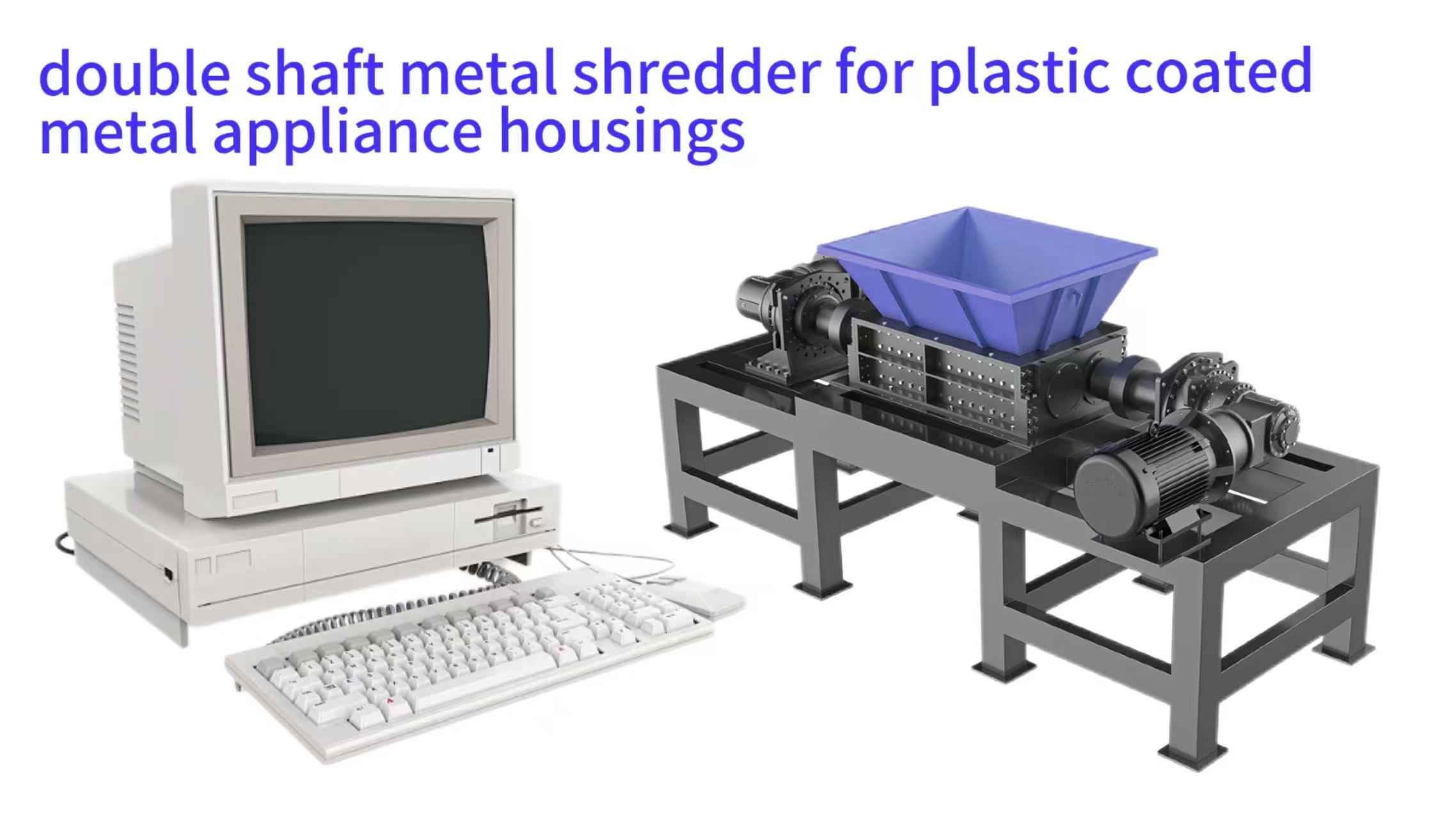
Processing discarded appliance housings, such as those from washing machines and refrigerators, presents a distinct challenge for recycling operations. These items are composite structures, typically featuring a thin-gauge steel shell coated with layers of plastic, paint, or polymer film for insulation and aesthetics. Conventional shredding equipment often fails to process this material efficiently, leading to persistent machine downtime, reduced throughput, and increased operational costs. The primary culprit is material winding, where long, pliable strips of plastic and metal laminate wrap around rotating components, jamming the mechanism. This article provides a detailed framework for selecting a specialized double-shaft metal shredder engineered to resist this specific failure mode. The following sections will analyze the material problem, explain the shredder's anti-winding design principles, and offer a complete guide for implementation, maintenance, and cost-benefit analysis to ensure a successful investment.
Material Characteristics & Winding Mechanism
Material Characteristics and Processing Challenges
Appliance housings are a complex waste stream. Their construction involves a metallic substrate, usually cold-rolled steel between 0.6 and 1.2 millimeters thick, coated with adherent plastics like polyvinyl chloride (PVC) or acrylonitrile butadiene styrene (ABS). This composite nature creates a unique set of mechanical behaviors during fragmentation. The metal core aims to fracture under shear stress, while the plastic coating exhibits high tensile strength and elongation, resisting clean separation and instead forming tenacious, stringy remnants. This fundamental mismatch in material response is the root cause of processing inefficiency and equipment strain in standard recycling systems not designed for such hybrids.
The physical geometry of the feedstock further complicates the task. These housings are large, hollow, and often have folded seams or attached brackets. Their low bulk density can cause feeding problems, leading to irregular infeed and sporadic loading of the cutting chamber. When such a large, flexible sheet enters a high-speed shredder, it is more likely to be caught and torn than cleanly sheared. This action initiates the winding process, where a leading edge of the torn material finds a point on a shaft or cutter to anchor itself, after which rotation gathers more material into a dense, obstructive bundle.
Mechanical Behavior of Composite Laminates
The bonding interface between the metal and plastic layers is a critical failure point. Under mechanical stress, this bond can delaminate partially but not completely. The result is not two separate, clean materials but a fragmented metal piece still attached to a web of stretched plastic film. This creates a hybrid debris with hooks and strands perfectly configured to snag on protruding machine parts. The plastic's viscoelastic properties mean it deforms under stress over time, allowing it to conform tightly to whatever it wraps around, making manual removal difficult and time-consuming.
Types of Winding in Metal Shredders
| Winding Type | Characteristics | Impact on Operation | Early Warning Signs |
|---|---|---|---|
| Axial Winding | Material spirals along shaft length, increasing effective diameter | Reduced cutter clearance, uneven wear, motor overload | Gradual amperage increase, unusual vibration |
| Localized Wrap-Around | Material wraps around individual cutters/breaker bars | Blunted cutting edges, reduced throughput, hot spots | Intermittent jamming, uneven discharge size |
Feedstock Geometry and Initial Fragmentation
The size and shape of appliance housings directly impact the first stage of shredding. Without pre-processing, their large surface area presents a significant challenge to the shredder's feed intake. They can bridge across the hopper opening, requiring manual intervention to push them into the cutting zone. Once engaged, a large sheet does not present a localized, well-supported cutting point to the blades. Instead, it flails and bends, absorbing impact energy and being drawn into the machine in an uncontrolled manner, which dramatically increases the probability of winding around the primary shredder shafts.
Manifestations of Winding and Wrap-Around
Winding typically manifests in two primary ways. Axial winding occurs when long strips spiral along the length of a rotating shaft, effectively creating a new, thicker diameter that interferes with the designed clearances in the cutting chamber. Localized wrap-around happens when material tightly winds around individual cutter discs or breaker bars, blunting their cutting edges and creating a solid mass that prevents other material from reaching the blades. Both conditions lead to a rapid increase in motor amperage, decreased output, and, if not addressed, catastrophic drive system failure.
Assessing Material Consistency and Contamination
Not all appliance housings are identical. Variations exist in steel gauge, coating type and thickness, and the presence of additional contaminants like foam insulation, rubber gaskets, or wiring. A reliable shredding system must handle this variability. Operators must assess their typical feedstock mix to determine the required robustness of the machine. A system tuned only for perfect, clean shells will struggle with real-world, contaminated material, leading to more frequent jams and winding incidents that disrupt continuous operation.
Shredder Mechanism Comparison
- 100-300 RPM shaft speed
- Impact/chopping action
- High tearing force
- Prone to winding with plastic-coated metals
- 10-30 RPM shaft speed
- Low-speed/high-torque shearing
- Controlled material feeding
- Minimizes plastic strand formation
The Winding Problem and Double-Shaft Shredder Mechanics
The phenomenon of winding is not random but a predictable outcome of applying inappropriate mechanical forces to a specific material. At its core, winding occurs when the machine's action on the material transitions from controlled shearing to uncontrolled tearing and pulling. A standard high-speed impact shredder or a single-shaft shear shredder often exacerbates this problem by using rapid, chopping motions that grab and fling material. In contrast, a properly configured double-shaft shredder is fundamentally designed to promote shear-dominated size reduction, which directly counteracts the forces that lead to winding.
Double-shaft shredders operate on the principle of low-speed, high-torque cutting. The two parallel shafts, fitted with intermeshing cutters, rotate inward at speeds typically between 10 and 30 revolutions per minute. This slow, powerful rotation draws material into the precise nip point between the cutters. The material is subjected to immense compressive and shear stresses at this controlled point, much like the action of powerful scissors. This focused shearing is more effective at cleanly cutting through both the metal and plastic layers simultaneously, minimizing the creation of long, tear-initiated strands that are the precursors to winding.
Shearing Versus Tearing Forces
The essential distinction lies in the force application. Shearing is a clean, through-thickness failure induced by two opposing forces acting parallel and very close to each other. It produces a predictable cut line and minimal plastic deformation outside the immediate shear zone. Tearing is a failure mode where a crack propagates uncontrolled through a material, often following the path of least resistance and requiring less instantaneous force but creating irregular, frayed edges. The intermeshing cutter design of a double-shaft machine is engineered to maximize shearing action and minimize the uncontrolled tearing that creates problematic strands.
Low-Speed, High-Torque Design Philosophy
The operational parameters are critical. The low rotational speed allows time for the material to be properly positioned and gripped by the cutters before the major force is applied. It prevents the "bouncing" or "slapping" effect seen in high-speed machines. The high torque, often delivered by a powerful gearbox or hydraulic motor, ensures that once the cut begins, the shafts do not stall. This continuous, unstoppable cutting motion is key to pushing through tough spots, like where a steel bracket is riveted to the housing, without creating a starting point for a wrap.
Intermeshing Shafts for Controlled Size Reduction
The geometry of the two shafts working together creates a self-regulating feed mechanism. As the cutters intermesh, they create a positive pulling action on the material, but within a confined space that restricts lateral movement. This controlled environment is where the actual size reduction is dictated by the physical clearance between the cutter tips and the machine's counter-knives. The material cannot easily escape this shear zone, ensuring it is cut to a relatively uniform size before being discharged, rather than being torn into random shapes and lengths.
Key Anti-Winding Components & Features
| Component | Anti-Winding Design Feature | Material/Construction | Benefit |
|---|---|---|---|
| Cutter Discs | Hooked/notched profile with chip breakers | Through-hardened tool steel / tungsten carbide wear caps | Breaks plastic strands, prevents wrap-around |
| Cutter Shaft | Precision alignment, zero micro-movement | High-tensile alloy steel forgings | Eliminates gaps for material to anchor |
| Hydraulic Drive | Variable speed + auto-reverse function | PLC-controlled hydraulic system | Self-clears minor tangles, no mechanical damage |
| Feed System | Hydraulic pusher ram + anti-bridging hopper | Reinforced steel hopper with anti-bridging spikes | Controlled feeding, promotes clean shearing |
Key Components of an Anti-Winding Double-Shaft Shredder
Beyond the basic principle of two intermeshing shafts, a shredder truly optimized to prevent winding incorporates a suite of specialized components and system integrations. These features work in concert to manage the challenging feedstock from the moment it enters the hopper until the shredded product is discharged. Selecting a machine with these specific attributes, rather than a generic double-shaft model, is crucial for achieving long-term, trouble-free operation with plastic-coated metals. Companies like MSW Technology leverage 15 years of field experience to integrate these proven features into robust machine designs.
The heart of the system is the cutting unit, but its effectiveness is enabled by supporting systems for feeding, discharge, and control. A machine that relies solely on gravity for feeding will struggle with large, flat panels. Discharge through a fine screen will quickly clog with plastic fuzz. Therefore, a holistic view of the machine's specification is necessary. The following components represent the critical differentiators between a standard shredder and one built for anti-winding performance in demanding recycling applications.
Cutter Shaft and Disc Assembly
The cutter shafts are the core load-bearing components. They are manufactured from high-tensile strength alloy steel forgings, heat-treated for optimal toughness and resistance to torsional bending. The individual cutter discs are slid onto the shaft and separated by spacing sleeves. They are keyed and locked in place with high-strength hydraulic tension bolts to prevent any micro-movement during operation, which is essential for maintaining precise cutter alignment and preventing gaps where material can sneak in and initiate winding. The entire assembly is supported by oversized, spherical roller bearings housed in rugged, sealed bearing blocks.
Specialized Anti-Winding Cutter Geometry
The cutter disc design is paramount. Anti-winding cutters often feature a hooked or notched profile on their periphery. This design serves a dual purpose: it aggressively grabs and pulls in large, flat items, and it incorporates strategic "chip breakers" or raised points. These breakers act to fracture any continuous strand of plastic that begins to form during the cut, proactively breaking it into shorter, unmanageable lengths before it can find an anchor point. The cutters are typically made from a through-hardened tool steel or feature welded-on wear caps of tungsten carbide for extended life against abrasive coatings.
Hydraulic Drive and Intelligent Control System
A hydraulic drive system offers significant advantages for this application. It provides infinitely variable speed control, allowing operators to fine-tune the shaft rotation for different material mixes. More importantly, hydraulic systems have a built-in pressure relief function; if an uncrushable object or severe jam is encountered, the system will stall without damaging the mechanical components. The programmable logic controller (PLC) can be set to automatically reverse the shafts for a few seconds if a preset pressure limit is reached, a feature that can unwind a minor tangle before it becomes a full blockage, significantly reducing operator intervention.
Forced Feed System and Hopper Design
To ensure consistent chamber loading and prevent bridging, a hydraulic pusher ram or a live-bottom feed conveyor is essential. This mechanism applies positive, controlled pressure to the feedstock, pushing it steadily into the cutting zone. This constant feed pressure helps present the material correctly to the cutters, supporting it during the initial bite to encourage shearing. The hopper itself is designed with steep, often reinforced walls and may include rotating "anti-bridging" spikes or arms to break up clumps of material before they reach the main shredding zone.
Complete Shredding System Integration Flow
(Reduce Feed Size)
(Controlled Infeed)
(Anti-Winding Shearing)
(Metal/Plastic Split)
Integration, Parameter Optimization, and Safety
An industrial shredder does not operate in isolation. Its performance is intrinsically linked to the upstream preparation of the material and the downstream handling of its output. A well-designed standalone machine can still underperform if integrated into a poorly planned system. Therefore, a successful installation requires careful consideration of the entire process flow, from pre-sorting to final product storage. This integrated approach ensures the shredder receives optimal feedstock and that its product can be efficiently moved to the next stage, whether that's storage, magnetic separation, or further processing.
Once installed, fine-tuning the operational parameters is key to unlocking peak efficiency and preventing issues. These parameters are not static; they may need adjustment based on changes in the material stream, such as seasonal variations or different appliance models being processed. Furthermore, operating heavy machinery like this demands a rigorous safety culture. Comprehensive safety protocols and physical guarding are non-negotiable to protect personnel from the significant hazards posed by rotating cutters, hydraulic systems, and flying debris.
Pre-Processing and System Feed Strategy
Implementing a pre-processing step can greatly enhance the primary shredder's efficiency. A pre-shear or large guillotine can be used to roughly cut appliance housings into halves or quarters. This reduces their planar size, eliminates hollow air pockets that cause feeding issues, and creates more edges for the shredder cutters to initially engage. This step transforms an awkward, winding-prone feed into a more granular, easily managed material stream, allowing the main shredder to operate at a higher and more consistent throughput with lower risk.
Operational Parameter Optimization for Different Materials
- Shaft Speed: 12-15 RPM
- Feed Rate: 70% capacity
- Hydraulic Pressure: High (80-85% max)
- Clean shearing of plastic layer
- Minimal strand formation
- 25% lower winding incidents
- Shaft Speed: 18-20 RPM
- Feed Rate: 60% capacity
- Hydraulic Pressure: Medium (70-75% max)
- Prevents foam compression
- Maintains throughput
- Reduced cutter wear
Optimizing Torque, Speed, and Feed Rate
The relationship between the hydraulic system pressure (which correlates to torque), shaft speed, and the feed ram's cycle rate is interactive. A starting point might involve setting the shafts to a moderate speed (e.g., 18 RPM) and the hydraulic pressure to a level known to handle the steel thickness. The feed ram is then set to extend at a rate that keeps the cutting chamber approximately 70-80% full. If the motor amperage or hydraulic pressure spikes too frequently, the feed rate is too high. If the chamber is often empty, the feed rate can be increased. This dynamic balancing act maximizes tonnage while keeping the system within safe operating limits.
Downstream Conveying and Material Separation
The output from the shredder is a mixture of fragmented steel, plastic chips, and possibly other contaminants. An enclosed, heavy-duty drag chain or rubber belt conveyor should immediately carry this material away. Placing a suspended overhead magnet on this conveyor effectively extracts the ferrous steel fraction. The remaining light fraction, predominantly plastic, can be further sorted using air classifiers or manual picking stations. Enclosing the discharge area and connecting it to a dust extraction system is vital for controlling airborne plastic particles and maintaining a safe, clean work environment.
Preventive Maintenance Protocol for Anti-Winding Shredders
Operational Monitoring and Preventive Maintenance
Sustained, reliable operation of an anti-winding shredder demands a disciplined maintenance regimen that shifts from reactive repair to predictive care. The harsh environment of shredding coated metals accelerates wear on specific components. A data-driven approach to monitoring machine health allows for the scheduling of maintenance during planned downtime, preventing costly unplanned breakdowns. This involves tracking key performance indicators, understanding normal wear patterns, and establishing clear protocols for inspection and component replacement.
Maintenance is not just about replacing worn parts; it also involves proactive measures to preserve the machine's anti-winding capabilities. For example, keeping cutter edges sharp is not only about productivity but also about ensuring clean shearing instead of tearing. A dull cutter will mash and pull material, increasing the very winding risk the machine was designed to avoid. Therefore, maintenance tasks are directly linked to sustaining the core performance promise of the equipment. The expertise required to develop such protocols is often rooted in extensive field service, a capability that firms like MSW Technology have honed over a decade and a half of supporting industrial shredding operations.
Establishing Baseline Parameters and Monitoring
Upon successful commissioning, baseline readings for critical parameters should be recorded. These include normal operating amperage for the main drive motor, typical hydraulic system pressure during a full-load cut, and the vibration signature of the bearing housings using a portable vibration analyzer. Daily operational logs should track hours run, tonnage processed, and any anomalies like unusual noises or frequent pressure spikes. Graphing this data over time reveals trends, such as a gradual increase in amperage indicating dulling cutters or rising bearing vibration signaling potential alignment issues or wear.
Blade Inspection, Rotation, and Replacement Protocol
The cutting discs are the primary consumable. A formal schedule should dictate inspection intervals, perhaps every 100-150 operating hours for this application. Inspection involves measuring the wear land on the cutter tips and checking for nicks or cracks. Many cutter designs are double-edged or can be rotated on the shaft to present a fresh cutting profile. A standardized procedure for safely locking out the machine, removing the shaft assembly, and rotating or replacing cutters is essential. When replacing, cutters should be changed in sets across the entire shaft to maintain balance, and the corresponding counter-knives should be inspected and replaced as needed to maintain the critical shear clearance.
Hydraulic and Lubrication System Maintenance
The hydraulic system's reliability is central to the forced feed and torque control. Regular maintenance includes checking fluid levels, testing fluid for viscosity and contamination (water or particulate), and replacing filters according to the pressure differential gauges. The centralized lubrication system for the shaft bearings must be checked to ensure it is delivering the correct amount of grease at set intervals. Over-greasing can be as detrimental as under-greasing, as excess grease can break down seals and allow contaminant ingress. These fluid and lubrication systems are the lifeblood of the machine's motion and power transmission.
Total Cost of Ownership (TCO) Analysis
| Cost Factor | Standard Shredder | Anti-Winding Shredder | Annual Cost Difference |
|---|---|---|---|
| Initial CAPEX | $150,000 | $225,000 | +$75,000 (One-time) |
| Unplanned Downtime | 200 hrs/year ($1,000/hr) | 25 hrs/year ($1,000/hr) | -$175,000 (Savings) |
| Cutter Replacement | 4 sets/year ($15,000/set) | 2 sets/year ($18,000/set) | -$24,000 (Savings) |
| Energy Consumption | 15% higher (inefficient operation) | Optimal efficiency | -$18,000 (Savings) |
Total Cost of Ownership and Procurement Framework
The final selection of an anti-winding shredder is a capital investment decision that must be evaluated beyond the initial purchase price. A comprehensive analysis considers the Total Cost of Ownership (TCO) over the machine's expected service life, typically 7-10 years. TCO includes capital expenditure, installation, energy consumption, routine maintenance, wear parts replacement, labor for operation and maintenance, and the significant cost of unplanned downtime. A machine with a higher initial price but superior reliability, lower energy use per ton, and longer wear part life can have a far lower TCO than a cheaper, less capable alternative.
Making an informed decision requires a structured procurement process. This process should move from defining technical requirements to validating supplier claims and finally negotiating a contract that protects the buyer's interests. The goal is to select a partner, not just a product—a supplier with the engineering depth to customize the solution, the inventory to support it with spare parts, and the service network to maintain it. This partnership approach minimizes long-term risk and ensures the equipment delivers the promised return on investment, especially for critical infrastructure in hard material shredding solutions.
Final Procurement Decision Process
Technical Evaluation and Supplier Assessment
Prospective buyers should develop a detailed technical specification document outlining their material analysis, required throughput (e.g., tons per hour), desired output size, and any site-specific constraints (power, space, emissions). This document is sent to qualified suppliers for quotation. The evaluation of responses should heavily weigh the supplier's specific experience with plastic-coated metal shredding. Requesting documented case studies, visitable reference sites, or even a small-scale trial with your own material provides tangible proof of capability that datasheets cannot.
Modeling Total Cost of Ownership
A robust TCO model should be constructed to compare proposals. Key inputs include: purchase price (FOB or delivered), estimated installation cost, annual energy consumption (based on motor power and estimated load factor), annual cost of cutter and wear liner replacement (based on supplier-provided life estimates and local pricing), estimated annual maintenance labor hours, and a value assigned to avoided downtime. This last factor is critical; if a superior machine prevents 50 hours of unplanned downtime per year, and downtime costs the operation $500 per hour in lost production and labor, that represents a $25,000 annual value that directly offsets a higher capital cost.
Final Contractual and Performance Guarantees
The final purchase agreement should be more than a sales order. It should include a technical appendix that specifies the agreed-upon machine configuration, material of construction for key components, and performance guarantees. These guarantees might stipulate that the machine will achieve a certain throughput on the defined feedstock while consuming less than a specified amount of energy per ton and producing output within a defined size range. Warranty terms for parts and labor should be explicit, and provisions for training, commissioning support, and after-sales service response times should be included. This formalizes the partnership and sets clear expectations for both parties, ensuring a successful project outcome from installation through years of operation.